PWM (Part 2) - Sound and Frequency with Piezo Buzzer
In previous tutorial, we had fun by controlling the brightness of a LED, using PWM. This time, we're going to have even more fun with a piezo buzzer, or a small speaker.
If you remember, with PWM, you can either vary the duty cycle or the frequency. Controlling the brightness of a LED, ie. produce a variable voltage on the average, can be done by having a constant frequency (high enough) and vary the duty cycle. This time, this will be the opposite: we'll have a constant duty cycle, and vary the frequency.
What is a piezo buzzer ?
It's a "component" with a material having piezoelectric ability. Piezoelectricity is the ability for a material to produce voltage when it get distorted. The reverse is also true: when you produce a voltage, the material gets distorted. When you stop producing a voltage, it gets back to its original shape. If you're fast enough with this on/off voltage setting, then the piezo will start to oscillate, and will produce sound. How sweet...
Constant duty cycle ? Why ?
So we now know why we need to vary the frequency. This will make the piezo oscillates more and less, and produces sounds at different levels. If you produce a 440Hz frequency, you'll get a nice A3.
- when setting the duty cycle to 10%: during a period, piezo will get distorted 10% on the time, and remain inactive 90% on the time. The oscillation proportion is low.
- when setting the duty cycle to 50%: the piezo is half distorted, half inactive. The oscillation proportion is high, because the piezo oscillates at the its maximal amplitude, it's half and equally distorted and inactive.
- when setting the duty cycle to 90%: the piezo will get distorted during 90% of a period, then nothing. The oscillation proportion is low again, because the proportion between distortion and inactivity is not equal.
So, to summary, what is the purpose of the duty cycle in our case ? The volume ! You can vary the volume of the sound by modifying the duty cycle. 0% will produce no sounds, 50% will be the max volume. Between 50% and 100% is the same as between 0% and 50%. So, when I say when need a constant duty cycle, it's not that true, it's just that we'll set it at 50%, so the chances we hear something are high :)
Let's produce sounds !
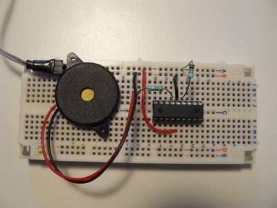
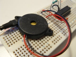
The schematics will use is exactly the same as on the previous post with the LED, except the LED is replaced with a piezo buzzer, like this:


By the way, how to observe the "duty cycle effect" on the volume ? Just program your PIC with the previous experiment one, which control the brightness of a LED, and power on the circuit. I wanted to show a video with sounds, but the frequency is too high, my camera can't record it...
Anyway, that's a little bit boring, we do want sounds...
Writing the software
forever loop has changed:var dword counter = 0
forever loop
for 100_000 using counter loop
pwm_set_frequency(counter)
-- Setting @50% gives max volume
-- must be re-computed each time the frequency
-- changes, because it depends on PR2 value
pwm1_set_percent_dutycycle(50)
end loop
end loop- we "explore" frequencies between 0 and 100 000 Hz, using a
counter - we use
pwm_set_frequency(counter)to set the frequency, in Hertz. It takes a dword as parameter (ie. you can explore a lot of frequencies...) - finally, as we want a 50% duty cycle, and since its value is different for each frequency setting, we need to re-compute it on each loop.
So, how does this look like ? Hope you'll like the sweet melody :)
http://www.youtube.com/watch?v=xZ9OhQUKGtQ
"Where can I download the files ?"
As usual, you'll need the latest jallib pack.