Blink A Led (Your First Project)
In this tutorial we are going to learn how to connect our first circuit and blink our first led.
Where to we start?
Let’s make a led blink on and off, how fun is that!
So, you’ve followed the installation guide and now have a Programming language (JALv2) + Libraries (JALLIB) + Editor. We will be using JALEdIt for our first example.
Setup your workspace
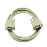
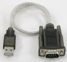
Start by getting out your programmer and connect it to your PC. Some connect by serial port, some connect via USB. I actually use a serial port programmer attached to a USB-to-Serial adapter to free up my serial port for other projects.
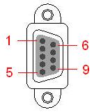
If you are using a serial port programmer you need to check that you have a regular serial cable and is not a null modem cable. Using your multimeter, check that each pin of your serial cable matches, if pins 7 & 8 are crossed, it is a null modem cable.
Get out your PIC microcontroller (we will now refer to it as a PIC). You can use PIC’s 16f877, 16f877A, 18F2550 , 18F452 or 18F4550 for this project since the port pin outs are the same for all of them. I will use 16f877A for this blink a led project.
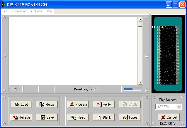
Now check PC connectivity to your programmer. Open your programming software on your PC, check the settings within your software to change the serial port number and programmer type (if available). Your programmer software may tell you that your board is connected, if not, put your PIC in your programmer and do some basic tests such as “read chip”, “blank / erase chip”
If you are using Micropro, click on “file” -> “port”, and “file” -> “programmer” -> (your programmer type). If you do not know the programmer type, you will have to guess until Micropro says something like “K149-BC board connected”, Put your PIC in your programmer and choose your PIC type from the “Chip Selector” text box. Now do some basic read/erase tests.
Build your circuit
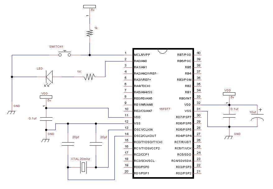
Well, it looks like we’re all set to go, so grab your breadboard and other components, put together the following circuit:
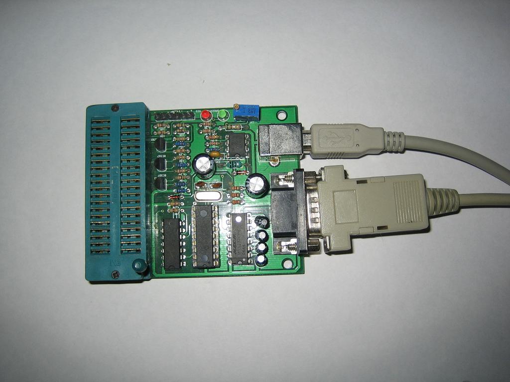
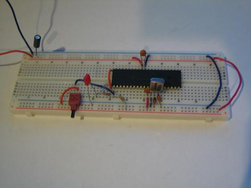
And here’s what it looks like. Notice the additional orange wire to the left of my PIC, this ensures that I always put my PIC in the correct position after programming. Do not connect your power 5v supply till your circuit is complete and checked over at least twice. You will burn your PIC if power is on while building your circuit. You will want an on/off switch for your power supply.
Your circuit is done, and it looks pretty, but it doesn’t do anything :o(..
Understand the jalv2 directory structure
First take a look at your jalv2 installation directory on your PC, wherever you installed it.
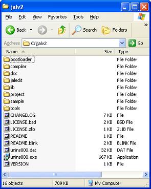
- compiler – holds the jalv2.exe compiler program for Windows and Linux to convert your JAL code to microcontroller hex code
- JALEdIt – JAL text editor where you will write your code. Note that you can also use Visual Studio Code for writing your code.
- lib – Device files and libraries to make things work
- sample – Working examples. For each PIC for which there is a device file there is also a blink-a-led sample file in the blink sub folder
- project – Some JALproject to play with
- doc JAL documentation.
Create yourself a folder called workspace, and in that folder create a folder called blink_a_led (eg. C:\jalv2\workspace\blink_a_led\)
Setup your editor & .jal file
Open up your favorite text editor. I will use JALEdIt. Run jaledit.exe from the JALEdIt directory. Start a new document, and save it in jalv2\workspace\blink_a_led\ and name it blink_a_led.jal (eg: C:\jalv2\workspace\blink_a_led\blink_a_led.jal)
Let’s write some code
So now we’re going to write the code that will make our led blink. All code will be in highlighted text. You can read more about JAL language in the jalv2.pdf file in directory 'compiler' of your Jallib installation.
Title & Author Block
Start out by writing a nice title block so everyone know’s who created it. Here’s an example Title block from Rob Hamerling’s and Rob Jansen's working 16f877a_blink.jal blink a led example in the sample directory. Every PIC has at least one working sample. You can see that two dashes “-“ declare a comment so your notes get ignored by the compiler. The character “;” can also be used for comments. We will comment our code as we go along so it is easier for us to read our own code.
-- ------------------------------------------------------
-- Title: Blink-a-led of the Microchip pic16f877a
-- Author: Rob Hamerling, Rob Jansen, Copyright (c) 2008..2022 all rights reserved.
-- Adapted-by:
-- Compiler:2.5r5
--
-- This file is part of jallib (https://github.com/jallib/jallib)
-- Released under the ZLIB license (http://www.opensource.org/licenses/zlib-license.html)
--
-- Description:
--    Simple blink-a-led program for Microchip pic16f877a
--    using an external crystal or resonator.
--
-- Sources:
--
-- Notes:
--  - Creation date/time: Sat Jan  8 17:03:04 2022
--  - This file is generated by 'blink-a-led.py' script! Do not change!
--
-- ------------------------------------------------------
Choose your PIC
Write the following code to choose the PIC you are using, change 16f877a to whatever PIC you have:
include 16f877a -- target PICmicroChoose your crystal speed
Write the following code according to the speed of the crystal you are using in your circuit. I suggest 20mhz for 16f877. You can check your chip’s datasheet for it’s max speed. Higher speeds may not work the way you want them to on a temporary breadboard.
-- This program assumes a 20 MHz resonator or crystal
-- is connected to pins OSC1 and OSC2.
pragma target clock 20_000_000     -- oscillator frequency
Configure PIC Settings
The following code sets some of the PIC’s internal settings, called fuses. A OSC setting of HS tells the PIC there is an external clock or crystal oscillator source. You must disable analog pins with enable_digital_io() , you don’t need to worry about the others.
pragma target OSC      HS                        -- crystal or resonator
pragma target WDT      DISABLED                  -- watchdog
pragma target DEBUG    DISABLED                  -- no debugging
pragma target BROWNOUT DISABLED                  -- no brownout reset
pragma target LVP      DISABLED                   -- no low voltage programming
--
-- The configuration bit settings above are only a selection, sufficient
-- for this program. Other programs may need more or different settings.
--
enable_digital_io()                 -- make all pins digital I/O
Choose an output pin
Let’s choose an output pin to control our led. As you can see from the circuit, our led is connected to pin #2. Let’s check our datasheet to find the pin name from the pin out diagram.
The PDF datasheet for this PIC and for all others can be downloaded from the microchip website. Here is the datasheet for this PIC https://www.microchip.com/en-us/product/PIC16F877A , and here is the pin out diagram from the datasheet:
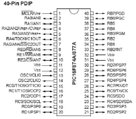
As you can see, we are using the pin RA0/ANO at pin #2. RA0 is the pin name we are looking for. AN0 is another name for this same pin (used in the analog to digital tutorial), but we can ignore it in this tutorial. In the JAL language RA0 is written as pin_A0
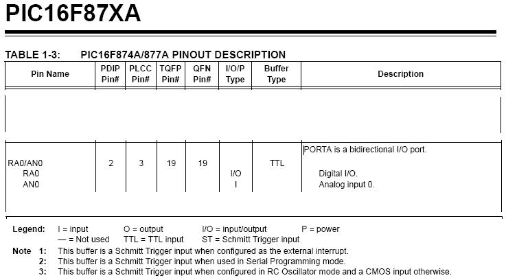
Now let’s read the details of this pin in the datasheet on page 10. As you can see RA0 is a TTL Digital I/O pin. We are checking this to make sure it is not a open drain output. Open drain outputs (like pin RA4) require a pull-up resistor from the pin to V+
Now write code for pin A0. We are writing an “alias” only because in the future we can refer to pin 2 (A0) as “led”. This way we no longer need to remember the name of the pin (except for the directional register in the next line of code we will write).
-- You may want to change the selected pin:
alias   led      is pin_A0
Configure the pin as an input or output
Now we must tell the PIC if this is an input or an output pin. The directional setting is always named (pin_ + pinname_ + direction). Since we are writing data to the port, to turn the led on, it is an output.
pin_A0_direction = outputWe could make an alias for this as well: “alias led_direction is pin_A0_direction”, then write “led_direction = output”. This way, we can change it from output to input in the middle of the program without knowing the pin name. But in this case, we will only use pin_A0_direction once in our program so there is no need to make an alias.
Write your program
So, now that we have the led under our control, let’s tell it what to do.
We will want our led to continue doing whatever we want it to do forever, so we’ll make a loop
forever loopIt is good practice to indent before each line within the loop for readability. 3 spaces before each line is the standard for Jallib.
In this loop, we will tell the led to turn on.
led = ONnow have some delay (250ms) a quarter of a second so we can see the led on.
_usec_delay(250_000)turn the led off again
led = OFFand have another delay before turning it back on again
_usec_delay(250_000)close our loop, when the PIC gets to this location, it will go back to the beginning of the loop
end loop
--
And that’s it for our code. Save your file, It should look something like this:
-- ------------------------------------------------------
-- Title: Blink-a-led of the Microchip pic16f877a
-- Author: Rob Hamerling, Rob Jansen, Copyright (c) 2008..2022 all rights reserved.
-- Adapted-by:
--
-- Compiler:2.5r5
--
-- This file is part of jallib (https://github.com/jallib/jallib)
-- Released under the ZLIB license (http://www.opensource.org/licenses/zlib-license.html)
--
-- Description:
--    Simple blink-a-led program for Microchip pic16f877a
--    using an external crystal or resonator.
--
-- Sources:
--
-- Notes:
--  - Creation date/time: Sat Jan  8 17:03:04 2022
--
-- ------------------------------------------------------
--
include 16f877a                     -- target PICmicro
--
-- This program assumes that a 20 MHz resonator or crystal
-- is connected to pins OSC1 and OSC2.
pragma target clock 20_000_000      -- oscillator frequency
--
pragma target OSC      HS                        -- crystal or resonator
pragma target WDT      DISABLED                  -- watchdog
pragma target DEBUG    DISABLED                  -- no debugging
pragma target BROWNOUT DISABLED                  -- no brownout reset
pragma target LVP      DISBLED                   -- no low voltage programming
--
-- The configuration bit settings above are only a selection, sufficient
-- for this program. Other programs may need more or different settings.
--
enable_digital_io()                 -- make all pins digital I/O
--
-- A low current (2 mA) led with 2.2K series resistor is recommended
-- since the chosen pin may not be able to drive an ordinary 20mA led.
--
alias  led       is pin_A0          -- alias for pin with LED
--
pin_A0_direction = OUTPUT
--
forever loop
   led = ON
   _usec_delay(250_000)
   led = OFF
   _usec_delay(250_000)
end loop
--
Compile your code to .hex
Now let’s get this beautiful code onto our PIC. Your PIC cannot understand JAL, but it does understand hex, this is what the compiler is for. The compiler takes people readable code and converts it to code your PIC can understand.
If you are using JALEdIt, click the compile menu at the top and choose compile. If you are using Visual Studio Code you can use ctrl-shift-b to compile your code.
If you are using your own text editor in Windows, you will need to open windows command prompt. Click start -> run and type cmd and press OK. Now type (path to compiler) + (path to your .jal file) + (-s) + (path to JALLIB libraries) + (options). Here’s an example for Windows and for Linux assuming you are running this from the directory where you have your JAL file:
- Windows: C:\jalv2\compiler\jalv2.exe blink_a_led.jal -s C:\jalv2\lib -no-variable-reuse
- Linux: ~/jalv2/compiler/bin/jalv2-x86-64 blink_a_led.jal -s ~/jalv2/lib -no-variable-reuse
The option -no-variable-reuse will use more PIC memory, but will compile faster but since computer are quite fast you and PIC memory is scarce you can leave out this option. In the documentation of the JAL compiler you find more compiler options that you can use.
If all this went OK, you will now have a blink_a_led.hex located in the same directory as your blink_a_led.jal, If there where errors or warnings, the compiler will tell you.
A error means the code has an problem and could not generate any .hex file. If there is a warning, the hex file was generated OK and may run on your PIC but the code should be fixed.
Write the hex file to your PIC
Take your PIC out of your circuit and put it in your programmer. With your programming software, open the blink_a_led.hex file. You should see that hex data loaded in your software. Now click the Write button. Your software will tell you when it is done. When using a PICKit programmer using the PICkitMinus software you can leave your PIC in your circuit, import the blink_a_led.hex file and program your PIC while it is in the circuit.
Let's Try It
If you removed your PIC for programming put your PIC back into your circuit, double check your circuit if you haven’t already, and make sure your PIC is facing the correct direction. Apply power to your circuit.
It’s alive! You should see your led blinking! Congratulations on your first JALv2 + JALLIB circuit!
Here's a youtube video of the result: http://www.youtube.com/watch?v=PYuPZO7isoo
I strongly suggest you do this tutorial next: Serial Port & RS-232 for communication.