SD Memory Cards
In this tutorial we will learn how to use an SD Card for mass data storage.
SD Card Introduction
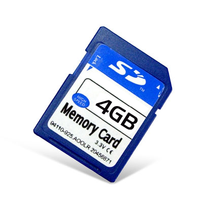
SD Cards (Secure Digital Cards) are quite popular these days for things like digital camera's, video camera's, mp3 players and mobile phones. Now you will have one in your project! The main advantages are: small size, large data storage capability, speed, cost. It has flash storage that does not require power to hold data. The current version of the sd card library that we will be using in this tutorial works with "standard capacity" sd cards up 4gb in size. I hope to find time to add "high capacity" and "extended capacity" capability to the library.
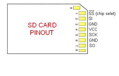
SD Card have 2 data transfer types "SD Bus" and "SPI Bus". Most PIC's have an SPI port. The "SD Bus" is faster, however uses more pins. We will be using SPI in our circuit. For more info on SPI read the tutorial in this book: SPI Introduction. The SPI mode for SD Cards is 1,1.
We are not responsible for your data or SD card. Make sure you have nothing important on your SD card before you continue.
These SD Cards are 3.3v devices, therefore a 5v to 3v conversion is needed between the PIC and the sd card. We will use resistors to do the conversion, however there are many other methods. See https://ww1.microchip.com/downloads/en/DeviceDoc/chapter%208.pdf for more information.
My favorite way of converting 5v to 3v is with 74HCT08. It must be HCT (not LS). 74LS08 will not work on a 3.3v power supply.
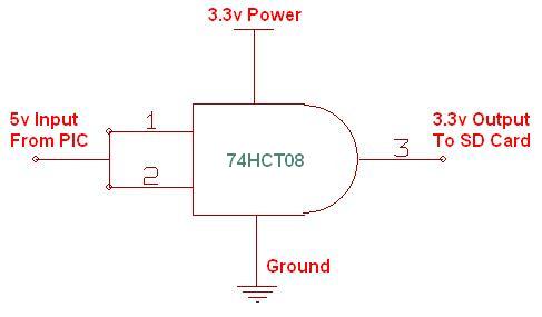
This circuit will use 16F877 If you are using a different PIC for your project, refer to the PIC's datasheet for pin output levels/voltage. For example, 18F452 has many pins that are 5v-input that give 3v-output. These pins show as "TTL / ST" - TTL compatible with CMOS level outputs in the datasheet and they will not require any voltage conversion resistors. If you are not sure, set a pin as an output, and make it go high then test with a volt meter.
Build a SD Card Slot
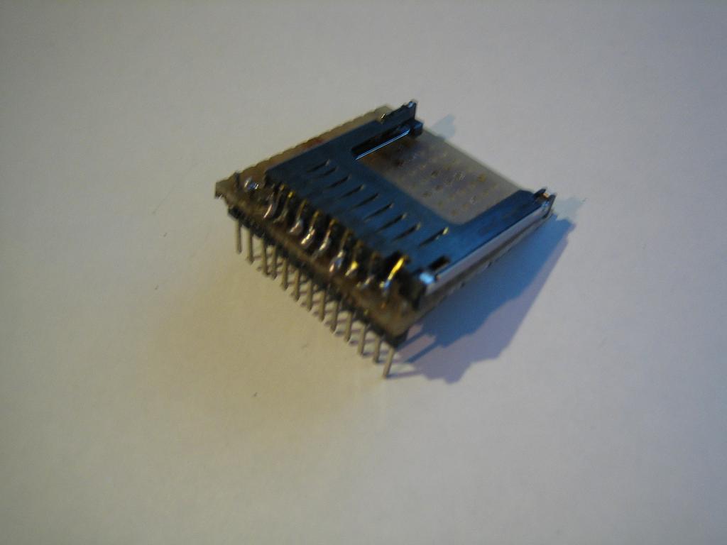
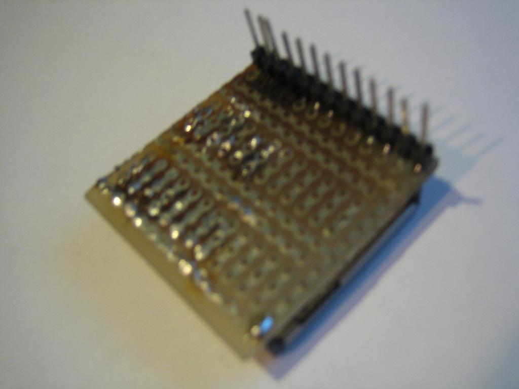
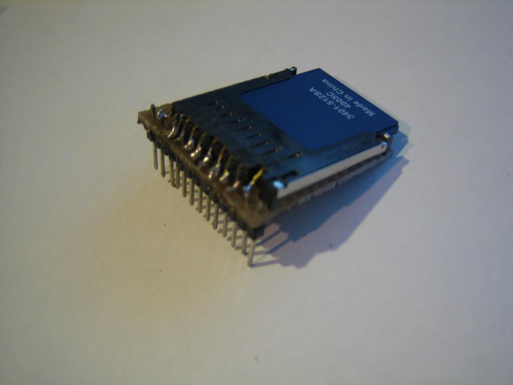
Before we can build our circuit, we will need to find ourselves an sd card slot that can plug into our breadboard. You can find pre-made sd card slots on ebay and other places around the net. It is quite easy to make your own anyways. I took one out of a broken digital camera and placed it on some blank breadboard and soldered on some pins. Here are some images of my sd card holder:
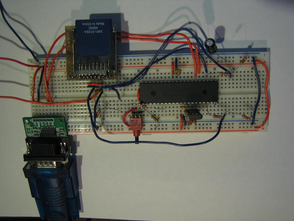
Build the circuit
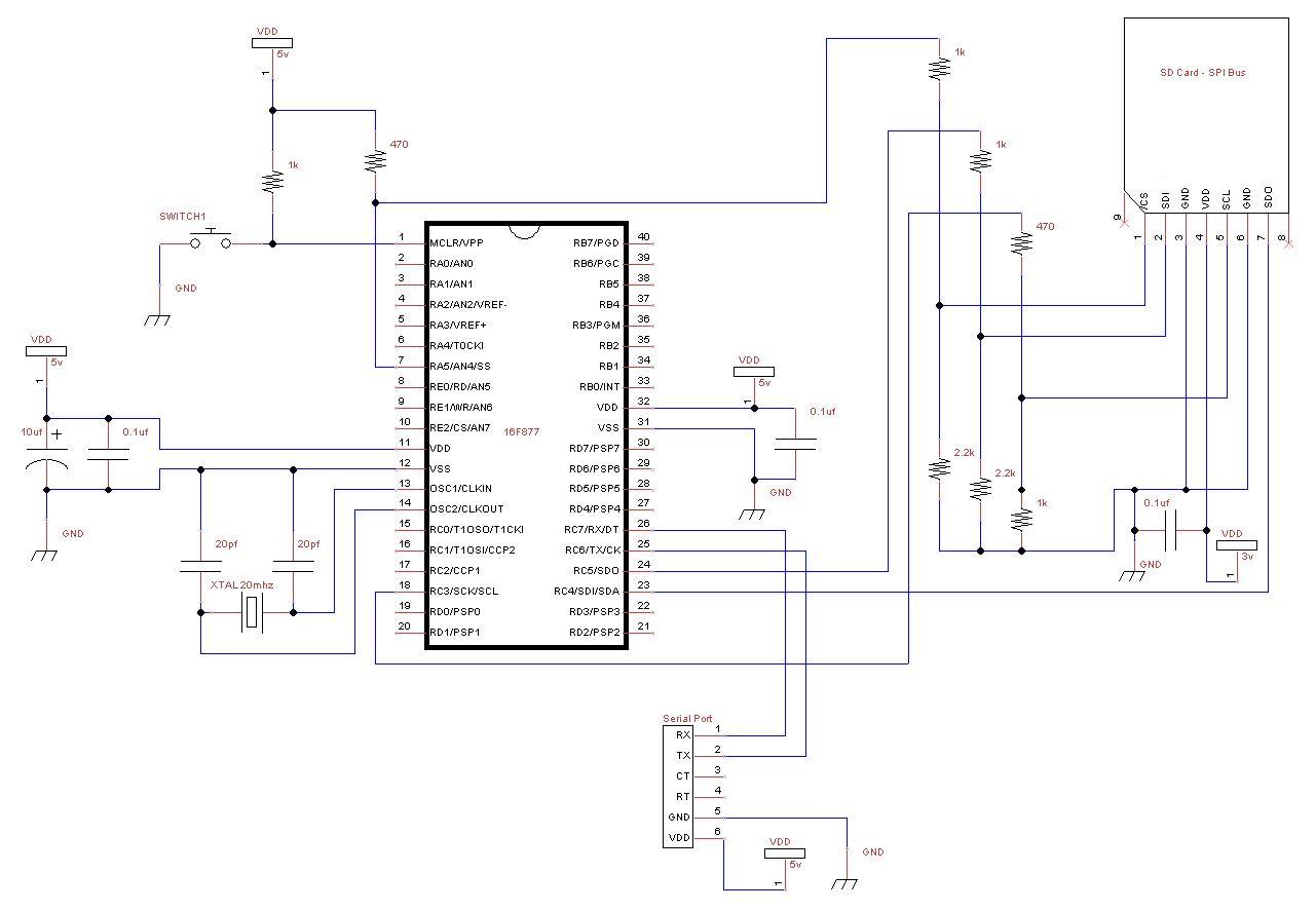
Follow this schematic for 16f877, if you are using another PIC, check the pin-outs for the SPI bus. The pin-outs of your pic will show SDI, SDO, SCL and SS. The pin SS is the chip select pin, you can use any pin for it but the others must stay the same.
Compile and write the software to your PIC
With the use of the sd card lib (sd_card.jal) and a sample file 16f877a_sd_card.jal, we can easily put one in our own circuit for mass data storage! You will find these files in the lib & sample directories of your jallib installation.
The most up to date version of the sample & library can be found at:
Sample file 16f877a_sd_card.jal from the sample directory.
Library file sd_card.jal from the lib directory.
Now that our circuit is built, lets test it and make sure it works before we continue with more details. Compile and program your pic with 16f877a_sd_card.jal from your jallib samples directory. If you are using another pic, change the "include 16f877a" line in 16f877a_sd_card.jal to specify your PIC before compiling.
Now that you have compiled it, burn the .hex file to your PIC
Power It Up
Plug your circuit into your PC for serial port communication at 38400 baud rate. Now turn it on. Press the reset button in your circuit, you should get a result similar to this:
Serial Output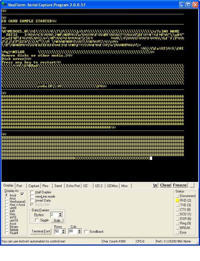
As you can see from the image, we got some actual readable data off the sd card as well as a bunch of junk. My sd card is formated with fat32, this is why I can actually read some of the data.
You now have a working sd card circuit!
Understand and modify the code
I'm just going to quickly go over some of the key points you need to know about sd cards. Open the sample file with an editor if you have not done so already.
The code in the sample file may change, therefore it may be different then what you see here. The sample file you have downloaded will always be tested and correct.
Include the chip
Specify the PIC you wish to use as well as your clock frequency
include 16f877a
--
pragma target OSC HS               -- HS crystal or resonator
pragma target clock 20_000_000     -- oscillator frequency
--
pragma target WDT  disabled
pragma target LVP  disabled
Disable all analog pins and wait for power to stabilize
enable_digital_io() -- disable all analog pins if any
_usec_delay (100_000) -- wait for power to stabilize
Setup serial port and choose baud rate 115200
-- setup uart for communication
const serial_hw_baudrate  = 115200   -- set the baud rate
include serial_hardware
serial_hw_init()
Include the print library
include print -- include the print librarySetup SPI Settings - The data transfer bus.
Here you may change the chip select pin "pin_SS" and "pin_SS_direction" to another pin. SDI, SDO and SCK must stay the same for the SPI hardware library.
You may notice that we are not defining/aliasing pins sdi, sdo and sck. We do not need to define them with a line like "alias pin_sdo is pin_c5" because they are set within the PIC and cannot be changed. If we use the SPI hardware library, we must use the SPI hardware pins. We only need to define there direction like this "pin_sdo_direction = output".
You may also choose the SPI rate. According to the SPI hardware library, you can use SPI_RATE_FOSC_4 SPI_RATE_FOSC_16, SPI_RATE_FOSC_64 or SPI_RATE_TMR. The fastest is FOSC_4 (oscillator frequency / 4). For the fastest speeds, it is a good idea to keep your SD Card as close to the PIC as possible.
include spi_master_hw         -- includes the spi library
-- define spi inputs/outputs
pin_sdi_direction = input    -- spi input
pin_sdo_direction = output   -- spi output
pin_sck_direction = output   -- spi clock
--
spi_init(SPI_MODE_11,SPI_RATE_FOSC_4) -- init spi, choose mode and speed

alias sd_chip_select is pin_a5
alias sd_chip_select_direction is pin_a5_direction
sd_chip_select_direction = output
Setup the SD Card library and settings
Select sd card settings & Include the library file, then initalize the sd card.
Some sd cards may require a 10ms (or more) delay every time you stop writing to the sd card, you can choose weather or not to have this delay. If you are doing many small writes and are worried about speed, you may set SD_DELAY_AFTER_WRITE to "FALSE".
-- setup the sd card
const bit SD_ALWAYS_SET_SPI_MODE = TRUE
const bit SD_DELAY_AFTER_WRITE = TRUE
include sd_card              -- include the sd card ide hard disk library
sd_init()                    -- initialize startup settings
Add a separator procedure, This will be used to display "------" onto the serial port between examples.
-- procedure for sending 80 "-----------------" via serial port
procedure seperator() is
   serial_hw_data = 13
   serial_hw_data = 10
   const byte str3[] = "--------------------------------------------------------------------------------"
   print_string(serial_hw_data, str3)
   print_crlf(serial_hw_data)
end procedure
It is always a good idea to send something to the serial port so we know the circuit is alive. Let's send "Hard Disk Sample Started"
-- Send something to the serial port
seperator()             -- send "----" via serial port
var byte start_string[] = "SD CARD SAMPLE STARTED"
print_string(serial_hw_data,start_string)
Declare some user variables
-- variables for the sample
var word step1
var byte data
EXAMPLES
OK, now that everything is setup, we are ready for some examples. I have left a few ways to read and write to SD Cards. The usage you choose may will on the PIC data space you have, and what your application is. On a smaller PIC, you will only be able to run examples #1, #2, #5 and #6. I'll explain as I go.
You will find that these examples are identical to the ones in the hard disk tutorial. This makes it easy for you to switch between using a SD Card and a hard disk.
Example #1 - Read data at sector 0
This is a low memory usage way of reading from the sd card, however it is slower then some of the other examples later on. This method requires the use of sd_start_read(), sd_data_byte, and sd_stop_read(). You'll see that the usage is quite simple.
The steps are:
- Start reading at a sector address. In this case, sector 0 (the boot sector)
- Loop many times while you read data. One sector is 512 bytes, we will read two sectors.
- Store each byte of data into the variable "data". You can retrieve the data by reading the pseudo variable sd_data_byte
- Do something with the data. Let's send it to the serial port.
- End the loop
- Tell the sd card we are done reading.
sd_start_read(0)           -- get sd card ready for read at sector 0
for 512 * 2 loop           -- read 2 sectors (512 * 2 bytes)
  data = sd_data_byte      -- read 1 bytes of data
  serial_hw_write(data)    -- send byte via serial port
end loop
sd_stop_read()             -- tell sd card you are done reading
OK, we're done our example, so lets separate it from the next one with the separator() procedure to send some "-----" characters and a small delay.
separator()                -- separate the examples with "----"
_usec_delay(500_000)       -- a small delay
Example #2 - Writing data
This example is similar to example #1, but we will be writing data to the sd card. It requires low memory usage. As with the first example, we will be required to use 3 procedures. sd_start_write(), sd_data_byte and sd_stop_write()
Here are the steps:
- Start writing at a sector address. I choose sector 20 since it seems that it will not mess up a fat32 formatted sd card, I could be wrong!
- Loop many times while you write your data. In this example, I am writing to 1 sector + 1/2 sector. The 2nd half of sector 2 will contain all 0's. The end of sector 2 will contain 0's because SD Cards will only write data in blocks of 512, and therefore any data you have there will be overwritten.
- Write some data. This time we are setting the value of the pseudo variable pata_hd_data_byte. Writing to this variable will actually send data to the hard disk. We are sending "A", so you will expect to read back the same data later on.
- End your loop
- Tell the SD Card we are done writing.
sd_start_write(20)         -- get sd card ready for write at sector 20
for 512 + 256 loop         -- loop 1 sector + 1 half sector (512 + 256 bytes)
  sd_data_byte = "A"       -- write 1 bytes of data
end loop
sd_stop_write()            -- tell sd card you are done reading
Now of course you will want to read your data back, which will be the same as in example #1, but at sector 20.
sd_start_read(20)          -- get sd card ready for read at sector 20
for 512 + 256 loop         -- loop 1 sector + 1 half sector (512 + 256 bytes)
 data = sd_data_byte       -- read 1 bytes of data
  serial_hw_write(data)    -- send byte via serial port
end loop
sd_stop_read()             -- tell sd card you are done reading
Example #3 - Read and write data using a sector buffer (a 512 byte array)
In this example, we will use a 512 byte array for reading and writing. This 512 byte array is called a sector buffer. This method is very fast, however it will require a PIC that can fit the 512 bytes of data in it's ram space. I find it is also easier to use. I suggest PIC18f4620 with the same schematic.
For writing, You will need only need to write data to the sector buffer array, then use the sd_write_sector_address() procedure.
Lets go through the steps, first for writing data:
- Loop 512 times (the size of the sector buffer)
- Set each data byte in the array
- End your loop
- Write the data to the hard disk at a sector address.
- Repeat the above to write more sectors.
-- fill the sector buffer with data
for 512 using step1 loop                     -- loop till the end of the sector buffer
   sd_sector_buffer[step1] = "B"             -- set each byte of data
end loop
-- write the sector buffer to sector 20
sd_write_sector_address(20)
Here we will write another sector (to sector 21, the next sector)
for 512 using step1 loop                     -- loop till the end of the sector buffer
   sd_sector_buffer[step1] = "C"             -- set each byte of data
end loop
-- write the sector buffer to sector 21
sd_write_sector_address(21)
OK, it's time to read back the data, which is exactly the opposite of writing. For reading, we will use the pata_read_sector_addres() procedure first, then we can read data from the sector buffer array.
- Request data from the SD Card at a sector address.
- Loop 512 times (the size of the sector buffer).
- Send each byte to the serial port.
- End your loop.
- Repeat the above to read more sectors.
-- read back the same sectors
-- read sector 20 into the sector buffer
sd_read_sector_address(20)
-- now send it to the serial port
for 512 using step1 loop                     -- loop till the end of the sector buffer
   serial_hw_write (sd_sector_buffer[step1]) -- send each byte via serial port
end loop
Here we will repeat the above to read the next sector (sector 21)
-- read sector 21 into the sector buffer
sd_read_sector_address(21)
-- now send it to the serial port
for 512 using step1 loop                     -- loop till the end of the sector buffer
   serial_hw_write (sd_sector_buffer[step1]) -- send each byte via serial port
end loop
EXAMPLE #4 - Another method for reading and writing sectors
Example #4 is pretty straight forward. I am not going to go into too much detail on this one. It is a combination of examples 2 and 3. It is about the same speed as example #3.
-- get sd card ready for write at sector 20
sd_start_write(20)
-- fill the sector buffer with data
for 512 using step1 loop                   -- loop till the end of the sector buffer
  sd_sector_buffer[step1] = "D"            -- set each byte of data
end loop
-- write the sector buffer to the sd card
sd_write_sector()
-- fill the sector buffer with new data
for 512 using step1 loop                   -- loop till the end of the sector buffer
  sd_sector_buffer[step1] = "E"            -- set each byte of data
end loop
-- write the sector buffer to the sd card
sd_write_sector()                          -- write the buffer to the sd card
-- tell sd card you are done writing
sd_stop_write()
--
-- read back both of the same sectors
-- get sd card ready for read at sector 20
sd_start_read(20)
-- read the sector into the sector buffer
sd_read_sector()
-- now send it to the serial port
for 512 using step1 loop                   -- loop till the end of the sector buffer
  serial_hw_write(sd_sector_buffer[step1]) -- send each byte via serial port
end loop
-- read the next sector into the sector buffer
sd_read_sector()
-- now send it to the serial port
for 512 using step1 loop                   -- loop till the end of the sector buffer
  serial_hw_write(sd_sector_buffer[step1]) -- send each byte via serial port
end loop
sd_stop_read()                             -- tell sd card you are done reading
Now you can put whatever you want on your SD Card, or possibly read lost data off of it.
If you want to read files stored on the card by your PC, there is a FAT32 library and there will be a tutorial soon so you can easily browse, read and write to files and folders stored on your card.
What are you waiting for, go build something cool!
Sources
The Jallib SD Card Library - Written by Matthew Schinkel