In the following tutorials, we're going to (try to)
have some fun with PWM. PWM stands for Pulse Width
Modulation, and is quite weird when you first face this (this was
at least my first feeling). So here's a brief explanation of what it is
about.
How does PWM look like ?...
PWM is about
switching one pin (or more) high and low, at different frequencies and
duty cycles. This is a on/off process. You can either vary:
the frequency,
or the duty cycle, that is the proportion where the pin
will be high
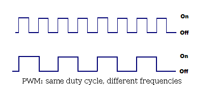
Figure 1. PWM: same duty cycle, different frequencies.
Both have a 50% duty cycle (50% on, 50% off), but the upper
one's frequency is twice the bottom
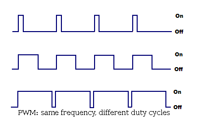
Figure 2. PWM: same frequency, different duty cycles
Three different duty cycle (10%, 50% and 90%), all at the same
frequency
But what is PWM for ? What can we do with it ? Many things,
like:
producing variable voltage (to control DC motor speed, for
instance)
playing sounds: duty cycle is constant, frequency is variable
playing PCM wave file (PCM is Pulse Code Modulation)
...
That said, we're now goind to experiment these two major
properties.