I²C (Part 3) - Implementing an I²C Slave
- if you send "a", it sends "b"
- if you send "b", it sends "c"
- if you send "z", it sends "{"1
Building the i2c master
Let's start with the easy part. What will master do ? Just collect characters from a serial link, and convert them to i2c commands. So you'll need a PIC to which you can send data via serial. I mean you'll need a board with serial com. capabilities. I mean we won't do this on a breadboard... There are plenty out there on the Internet, pick your choice.
My board looks like this:
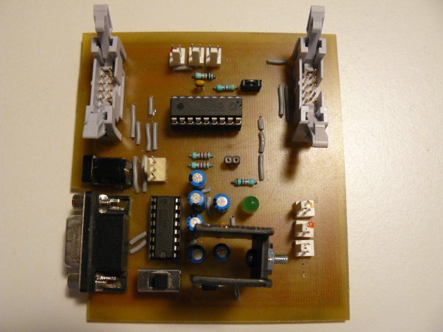
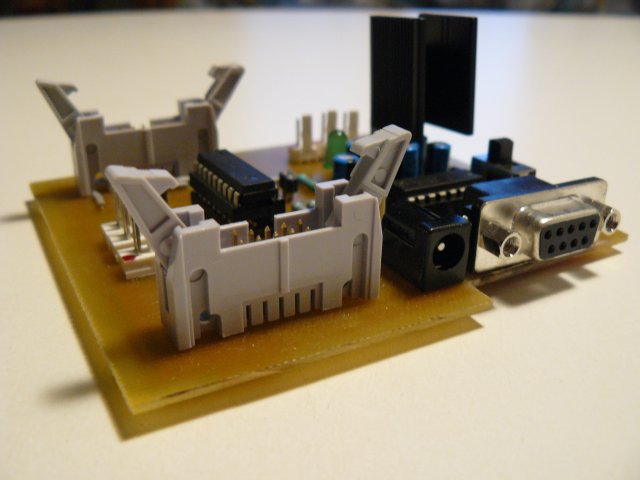
Two connectors are used for earch port, PORTA and PORTB, to plug daughter boards, or a breadboard in our case.
The i2c initialization part is quite straight forward. SCL and SDA pins are declared, we'll use a standard speed, 400KHz:
-- I2C io definition
var volatile bit i2c_scl            is pin_b4
var volatile bit i2c_scl_direction  is pin_b4_direction
var volatile bit i2c_sda            is pin_b1
var volatile bit i2c_sda_direction  is pin_b1_direction
-- i2c setup
const word _i2c_bus_speed = 4 ; 400kHz
const bit _i2c_level = true   ; i2c levels (not SMB)
include i2c_software
i2c_initialize()
We'll also use the level 1 i2c library. The principle is easy: you declare two buffers, one for receiving and one for sending bytes, and then you call procedure specifying how many bytes you want to send, and how many are expected to be returned. Joep has written a nice post about this, if you want to read more about this. We'll send one byte at a time, and receive one byte at a time, so buffers should be one byte long.
const single_byte_tx_buffer = 1 -- only needed when length is 1
var byte i2c_tx_buffer[1]
var byte i2c_rx_buffer[1]
include i2c_level1
What's next ? Well, master also has to read chars from a serial line. Again, easy:
const usart_hw_serial = true
const serial_hw_baudrate = 57_600
include serial_hardware
serial_hw_init()
-- Tell the world we're ready !
serial_hw_write("!")
So when the master is up, it should at least send the "!" char.
Then we need to specify the slave's address. This is a 8-bits long address, the 8th bits being the bit specifying if operation is a read or write one (see part 1 for more). We then need to collect those chars coming from the PC and sends them to the slave.
The following should do the trick (believe me, it does :))
var byte icaddress = 0x5C   -- slave address

forever loop
   if serial_hw_read(pc_char)
   then
      serial_hw_write(pc_char)  -- echo
      -- transmit to slave
      -- we want to send 1 byte, and receive 1 from the slave
      i2c_tx_buffer[0] = pc_char
      var bit _trash = i2c_send_receive(icaddress, 1, 1)
      -- receive buffer should contain our result
      ic_char = i2c_rx_buffer[0]
      serial_hw_write(ic_char)
   end if
end loop
The whole program is available on under the name 16f88_i2c_sw_master_echo.jal in the sample directory of your Jallib installation.
Building the i2c slave
So this is the main part ! As exposed on first post, we're going to implement a finite state machine. jallib comes with a library where all the logic is already coded, in a ISR. You just have to define what to do for each state encountered during the program execution. To do this, we'll have to define several callbacks, that is procedures that will be called on appropriate state.
Before this, we need to setup and initialize our slave. i2c address should exactly be the same as the one defined in the master section. This time, we won't use interrrupts on Start/Stop signals; we'll just let the SSP module triggers an interrupts when the i2c address is recognized (no interrupts means address issue, or hardware problems, or...). Finally, since slave is expected to receive a char, and send char + 1, we need a global variable to store the results. This gives:
include i2c_hw_slave

const byte SLAVE_ADDRESS = 0x5C
i2c_hw_slave_init(SLAVE_ADDRESS)

-- will store what to send back to master
-- so if we get "a", we need to store "a" + 1
var byte data- state 1: master initiates a write operation (but
does not send data yet). Since no data is sent, slave should just
do... nothing (slave just knows someone wants to send
data).
procedure i2c_hw_slave_on_state_1(byte in _trash) is pragma inline -- _trash is read from master, but it's a dummy data -- usually (always ?) ignored end procedure - state 2: master actually sends data, that is one
character. Slave should get this char, and process it (char +
1) for further sending.
procedure i2c_hw_slave_on_state_2(byte in rcv) is pragma inline -- ultimate data processing... :) data = rcv + 1 end procedure - state 3: master initiates a read operation, it wants to
get the echo back. Slave should send its processed
char.
procedure i2c_hw_slave_on_state_3() is pragma inline i2c_hw_slave_write_i2c(data) end procedure - state 4: master still wants to read some
information. This should never occur, since one char is sent and
read at a time. Slave should thus produce an
error.
procedure i2c_hw_slave_on_state_4() is pragma inline -- This shouldn't occur in our i2c echo example i2c_hw_slave_on_error() end procedure - state 5: master hangs up the connection. Slave
should reset its state.
procedure i2c_hw_slave_on_state_5() is
   pragma inline
   data = 0
end procedure
Finally, we need to define a callback in case of error. You could do anything, like resetting the PIC, and sending log/debug data, etc... In our example, we'll blink forever:
procedure i2c_hw_slave_on_error() is
   pragma inline
   -- Just tell user user something's got wrong
   forever loop
      led = on
      _usec_delay(200000)
      led = off
      _usec_delay(200000)
   end loop
end procedure
Once callbacks are defined, we can include the famous ISR library.
include i2c_hw_slave_isr- include i2c_hw_slave, and setup your slave
- define your callbacks,
- include the ISR
- i2c_hw_slave.jal
- i2c_hw_slave_isr.jal
- 16f88_i2c_sw_master_echo.jal
- 16f88_i2c_hw_slave_echo.jal
All those files and other dependencies are also available in latest jallib-pack (see jallib downloads)
Connecting and testing the whole thing...
As previously said, the board I use is ready to be used with a serial link. It's also i2c ready, I've put the two pull-ups resistors. If your board doesn't have those resistors, you'll have to add them on the breadboard, or it won't work (read part 2 to know and see why...).
I use a connector adapted with a PCB to connect my main board with my breadboard. Connector's wires provide power supply, 5V-regulated, so no other powered wires it required.
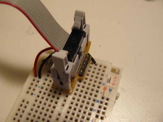
Connector, with power wires
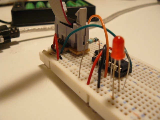
Everything is ready...
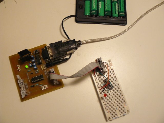
Crime scene: main board, breadboard and battery pack
Once connected, power the whole and use a terminal to test it. When pressing "a", you'll get a "a" as an echo from the master, then "b" as result from the slave.

What now ?
We've seen how to implement a simple i2c hardware slave. The ISR library provides all the logic about the finite state machine. You just have to define callbacks, according to your need.
i2c is a widely used protocol. Most of the time, you access i2c devices, acting as a master. We've seen how to be on the other side, on the slave side. Being on the slave side means you can build modular boards, accessible with a standard protocol.