Hard Disks - IDE/PATA
IDE Paralel ATA hard disk drive tutorial
Introduction to hard disks drives
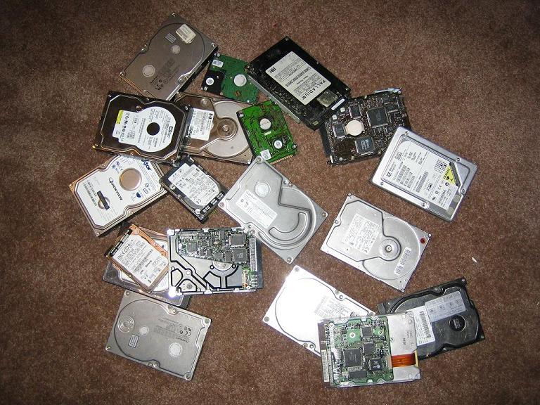
If your are like me, you have too many old hard disks laying around. I have gathered quite a collection of drives from PC's I have had in the past. Now you can dust off your drives and put them in your circuit. I have extra drives ranging in size from 171MB to 120GB.
Before you start, make sure you use a drive you do not care about. We are not responsible for your drive of the data that is on it.
You can find more general info at http://en.wikipedia.org/wiki/Parallel_ATA, and you can find more detailed technical info at http://www.gaby.de/gide/IDE-TCJ.txt
Drive Types - PATA vs SATA
There are two types of hard disks PATA (parallel ata) and SATA (serial ata). In this tutorial we will use PATA, these drives use a 40 pin IDE connector. The newer type of drive SATA has only 7 pins but there is no Jallib library for these drives at the moment. Both types of hard disks are available with massive amounts of data space.
Drive Data Size
The current jallib library will accept drives up to 128GB. The 128GB limit is due to and addressing limitation, this is the 28 bit addressing limitation.The max address you will be able to reach is hex 0xFFFFFFF. If you multiply this address by 512 bytes (1 sector) you get a max size of 137,438,952,960 bytes, yes this does equal 128GB. Eventually I may upgrade the library for 48bit addressing which will allow up to a max drive size hex 0xFFFFFFFFFFFF * 512 = 128PB (Petabytes). But now that I think about it, 128 GB should be enough!
Actual Size
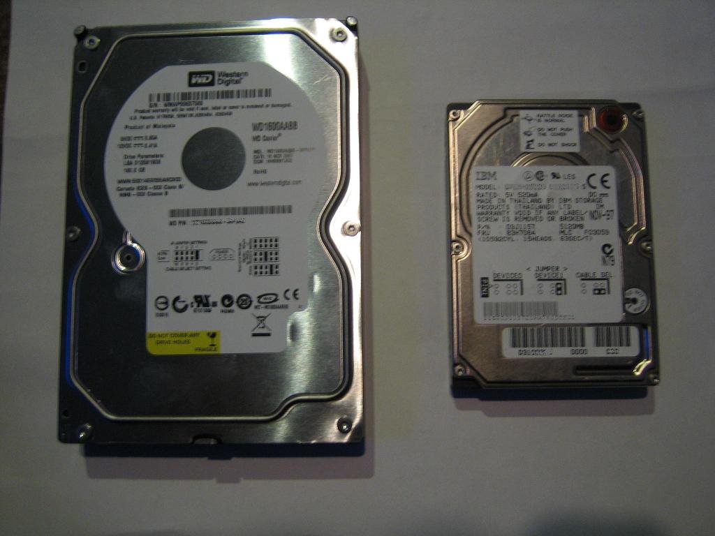
The most common drive sizes today are 3.5" and 2.5". The 3.5 inch drives are commonly used in desktop computers, 2.5" drives are used in laptops. The 2.5" drives are nice for your circuit because they do not require a 12v supply voltage, and they use much less power.
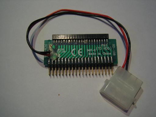
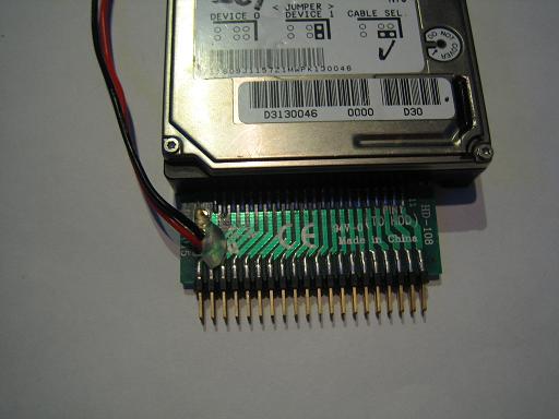
If you wish to use a 2.5" laptop hard drive, you may need a 2.5" to 3.5" IDE adapter like this one:
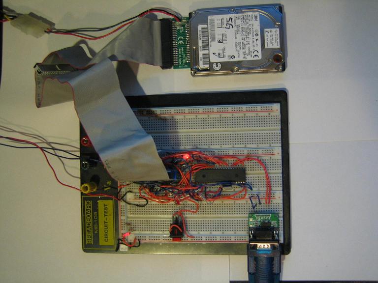
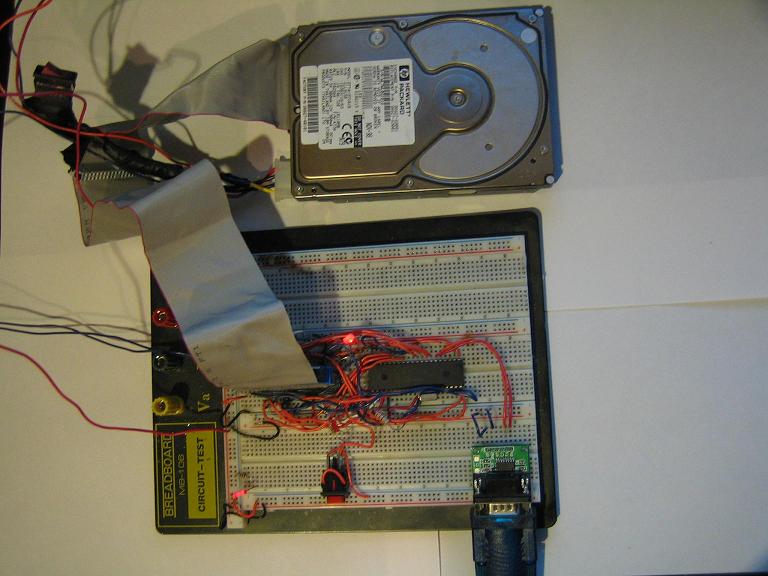
Build a breadboard connector
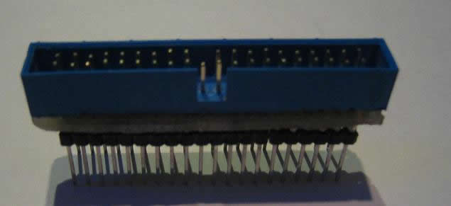
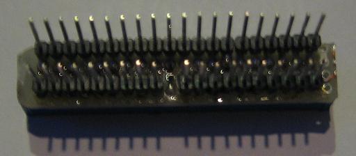
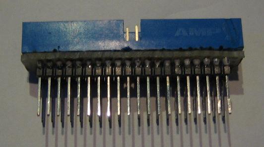
Now, if your going to put one of these into your circuit, you'll need to plug the drive into your breadboard. I took a 40pin IDE connector off an old motherboard. The easiest way to get large components of a board is to use a heat gun on the bottom side of the board to melt the solder on all pins at once.
Now take this connector and stick it into some blank breadboard and add some pins. The blank breadboard I cut is 4 holes wide by 20 long. Put the connector in the middle and connect the pins on the outside, join each pin with each pin of the connector.
Of course you will also need a 40pin IDE cable, I like the ones with the notch so you don't plug it in backwards. Here's the one I made:
Circuit Power
It is very important that you have enough power to drive your circuit. Hard drives need a lot of amps to run, especially the 3.5" drives, so make sure you have a decent 5v and 12v power supply. I suggest that you DO NOT use your PC's power supply to drive your circuit. You can easily short circuit your power supply and blow up your PC. If you really insist on doing this, you better put a fuse on both 5v and 12v between your PC and your circuit. Just remember that I told you not to!
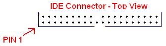
IDE Connector Pin-out
Pin 1 on the IDE cable is the red stripe. Here the pin out for the male connector I took off a motherboard:
Build the circuit
| PIN | FUNCTION | PIN | FUNCTION |
|---|---|---|---|
| 1 | /RESET | 2 | GND |
| 3 | D7 | 4 | D8 |
| 5 | D6 | 6 | D9 |
| 7 | D5 | 8 | D10 |
| 9 | D4 | 10 | D11 |
| 11 | D3 | 12 | D12 |
| 13 | D2 | 14 | D13 |
| 15 | D1 | 16 | D14 |
| 17 | D0 | 18 | D15 |
| 19 | GND | 20 | NO PIN |
| 21 | 22 | GND | |
| 23 | /IOWR - READ Pin | 24 | GND |
| 25 | /IORD - Write Pin | 26 | GND |
| 27 | 28 | ALE - 1K resistor to 5v | |
| 29 | 30 | GND | |
| 31 | 32 | ||
| 33 | A1 | 34 | |
| 35 | A0 | 36 | A2 |
| 37 | /CS0 (to 5v) | 38 | /CS1 (to GND) |
| 39 | ACT - BUSY LED | 40 | GND |
Build the circuit below. As you can see it is quite simple. As you can see, it only requires 3 resistors, a led and a bunch of wire. You can put a reset button on the IDE connector if you like, but I have found no use for it so I connect it direct to 5v.
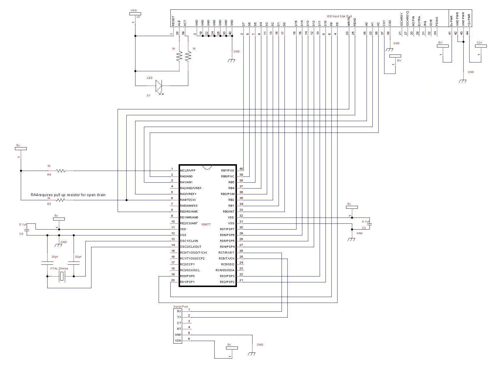
Here's what the completed circuit should look like (don't turn on the power yet):
Compile and write the software to your PIC
The hard disk lib (pata_hard_disk.jal) and a sample file (16f877_pata_hard_disk.jal) will be needed for this project. You will find these files in the lib & sample directories of your jallib installation.
The most up to date version of the sample & library can be found in the jallib relase.
Sample file 16f877a_pata_hard_disk.jal in the lib directory.
Library file pata_hard_disk.jal in the sample directory.
Now lets test it and make sure it works. Compile and program your pic with 16f877_sd_card.jal from your jallib samples directory. If you are using another pic, change the "include 16f877" line in 16f877_sd_card.jal to specify your PIC before compiling.
Now that you have compiled it, burn the .hex file to your PIC with your programmer
Power It Up
Plug your circuit into your PC for serial port communication at 115200 baud rate. Now turn it on. You should get data similar to the image below onto your serial port. You will also hear the hard drive turn on and off because of one of the examples in the sample file.
Serial Port Output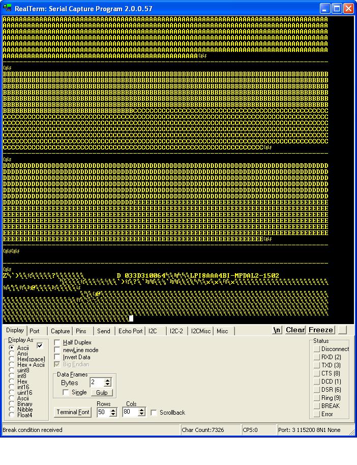
Some of the data is not shown in the above image. If your disk is formatted with fat32 you may be able to see some readable data from the boot sector. On my drive formatted with fat32 I can read "Invalid partition table Error loading operating system" (not shown in the image). The AA BB CC DD EE are read/write examples that will be shown below. The last set of data is from the Identify Drive command.
You now have a working hard disk circuit!
Understand and modify the code
I will go over some of the key points you need to know about hard disk coding. Open the sample file with an editor if you have not done so already. The code in the sample file may change, therefore it may be different then what you see here. The sample file you have downloaded will always be tested and correct.
Include the chip
Select the PIC you wish to use and your clock frequency
-- include chip
include 16F877a                    -- target PICmicro
pragma target clock 20_000_000     -- oscillator frequency
-- configure fuses
pragma target OSC  HS              -- HS crystal or resonator
pragma target WDT  disabled        -- no watchdog
pragma target LVP  disabled        -- no Low Voltage Programming
Disable all analog pins and wait for power to stabilize
enable_digital_io() -- disable all analog pins if any
_usec_delay (100_000) -- wait for power to stabilize
Setup serial port and choose baud rate 115200
-- setup uart for communication
const serial_hw_baudrate  = 115200   -- set the baud rate
include serial_hardware
serial_hw_init()include print -- include the print librarySetup the hard disk library constants/settings
The registers Alternate Status, Digital Output, and Drive Address registers will only be used by advanced users, so keep the default PATA_HD_USE_CS0_CS1_PINS = FALSE
The pins /iowr, /iord, /cs0, /cs1 are active low pins that are supposed to require an inverter. If you leave PATA_HD_NO_INVERTER = TRUE, the PIC will do the inversion for you. You will most likely want to keep the default "TRUE".
-- setup hard disk library

-- uses additional code space to add a speed boost to sector_read procedures
const bit PATA_HD_READ_EXTRA_SPEED = FALSE

-- set true if you will use Alternate Status,
-- Digital Output or Drive Address registers
const byte PATA_HD_USE_CS0_CS1_PINS = FALSE

-- if true, an external inverter chip is not
-- needed on /iowr, /iord, /cs0, /cs1 pins
const bit PATA_HD_NO_INVERTER = TRUE
Setup pin assignments
Yes, pata hard disks have a lot of pins. You will need two full 8pin port's (port B and port D of 16F877) for data transfer, three register select pins, one read pulse pin and one write pulse pin. A total of 19 io pins. I am able to comment out cs1/cs0 and save pins because of the constant we set.
-- pin assignments
alias     pata_hd_data_low              is portb   -- data port (low bits)
alias     pata_hd_data_low_direction    is portb_direction
alias     pata_hd_data_high             is portd   -- data port (high bits)
alias     pata_hd_data_high_direction   is portd_direction

alias     pata_hd_a0                    is pin_a3
alias     pata_hd_a0_direction          is pin_a3_direction
alias     pata_hd_a1                    is pin_a1
alias     pata_hd_a1_direction          is pin_a1_direction
alias     pata_hd_a2                    is pin_a0
alias     pata_hd_a2_direction          is pin_a0_direction

alias     pata_hd_iowr                  is pin_e0
alias     pata_hd_iowr_direction        is pin_e0_direction
alias     pata_hd_iord                  is pin_a4
alias     pata_hd_iord_direction        is pin_a4_direction

;alias     pata_hd_cs1                   is pin_a3
;alias     pata_hd_cs1_direction         is pin_a3_direction
;alias     pata_hd_cs0                   is pin_a4
;alias     pata_hd_cs0_direction         is pin_a4_direction

pata_hd_a0_direction = output    -- register select pin
pata_hd_a1_direction = output    -- register select pin
pata_hd_a2_direction = output    -- register select pin

pata_hd_iowr_direction = output  -- used for write pulse
pata_hd_iord_direction = output  -- used for read pulse

;pata_hd_cs1_direction = output   -- register select pin
;pata_hd_cs0_direction = output   -- register select pin
Now include the library
include pata_hard_disk           -- include the parallel ata ide hard disk library
pata_hd_init()                   -- initialize startup settings
Add a separator procedure, This will be used to display "------" onto the serial port between examples.
-- procedure for sending "-----------------" via serial port
procedure separator() is
   serial_hw_data = 13
   serial_hw_data = 10
   const byte str3[] = "---------------------------------------"
   print_string(serial_hw_data, str3)
   print_crlf(serial_hw_data)
end procedure
It is always a good idea to send something to the serial port so we know the circuit is alive. Let's send "Hard Disk Sample Started"
-- Send something to the serial port
separator()             -- send "----" via serial port
var byte start_string[] = "HARD DISK SAMPLE STARTED"
print_string(serial_hw_data,start_string)-- variables for the sample
var word step1
var byte dataEXAMPLES
OK, now that everything is setup, we are ready for some examples.
You will find that these examples are identical to the ones in the SD Card tutorial. This makes it easy for you to switch between using a hard drive and a SD Card.
Before we get stated, you may want to get to know your hard drive and it's size. This way you will know what the maximum addressable sector is.
On newer drives, you will see on the front sticker the number of LBA's. This is the number of sectors on the drive. We must subtract one from the number of LBA's to get the highest addressable sector since the 1st sector is at address 0. My drive says "60058656" LBA's, therefore the last sector is at 60058656 - 1.
Each sector is 512 bytes, so the actual size of this drive is 60058656 * 512 = 30GB
On the sticker of some older drives, you will see CYL, HEADS,SEC/T. You can calculate the number of sectors with: (cylinders * heads * sectors per track). Then you may multiply that by 512 if you wish to get the size of the drive in bytes.
I have left a few ways to read and write to hard disks. The usage you choose may will on the PIC data space you have, and what your application is. On a smaller PIC, you will only be able to run examples #1, #2, #5 and #6. I'll explain as I go.
Example #1 - Read data at sector 0
This is a low memory usage way of reading from the hard disk, however it is slower then some of the other examples later on. This method requires the use of pata_hd_start_read(), pata_hd_data_byte, and pata_hd_stop_read(). You'll see that the usage is quite simple.
The steps are:
- Start reading at a sector address. In this case, sector 0 (the boot sector)
- Loop many times while you read data. One sector is 512 bytes, we will read two sectors.
- Store each byte of data into the variable "data". You can retrieve the data by reading the pseudo variable pata_hd_data_byte
- Do something with the data. Let's send it to the serial port.
- End the loop
- Tell the hard disk we are done reading. The hard disk light will go out at this step.
pata_hd_start_read(0)      -- get sd card ready for read at sector 0
for 512 * 2 loop           -- read 2 sectors (512 * 2 bytes)
  data = pata_hd_data_byte -- read 1 bytes of data
  serial_hw_write(data)    -- send byte via serial port
end loop
pata_hd_stop_read()        -- tell sd card you are done reading
OK, we're done our example, so lets separate it from the next one with the separator() procedure to send some "-----" characters and a small delay.
separator()                -- separate the examples with "----"
_usec_delay(500_000)       -- a small delay
Example #2 - Writing data
This example is similar to example #1, but we will be writing data to the hard disk. It requires low memory usage. As with the first example, we will be required to use 3 procedures. pata_hd_start_write(), pata_hd_data_byte and pata_hd_stop_write()
Here are the steps:
- Start writing at a sector address. I choose sector 20 since it seems that it will not mess up a fat32 formatted drive, I could be wrong!
- Loop many times while you write your data. In this example, I am writing to 1 sector + 1/2 sector. The 2nd half of sector 2 will contain all 0's. The end of sector 2 will contain 0's because hard disks will only write data in blocks of 512, and therefore any data you have there will be overwritten.
- Write some data. This time we are setting the value of the pseudo variable pata_hd_data_byte. Writing to this variable will actually send data to the hard disk. We are sending "A", so you will expect to read back the same data later on.
- End your loop
- Tell the hard disk we are done writing. The hard disk light will go out at this step.
pata_hd_start_write(20)    -- get sd card ready for write at sector 20
for 512 + 256 loop         -- loop 1 sector + 1 half sector (512 + 256 bytes)
  pata_hd_data_byte = "A"  -- write 1 bytes of data
end loop
pata_hd_stop_write()       -- tell sd card you are done reading
Now of course you will want to read your data back, which will be the same as in example #1, but at sector 20.
pata_hd_start_read(20)          -- get sd card ready for read at sector 20
for 512 + 256 loop         -- loop 1 sector + 1 half sector (512 + 256 bytes)
  data = pata_hd_data_byte       -- read 1 bytes of data
  serial_hw_write(data)    -- send byte via serial port
end loop
pata_hd_stop_read()             -- tell sd card you are done reading
Example #3 - Read and write data using a sector buffer (a 512 byte array)
In this example, we will use a 512 byte array for reading and writing. This 512 byte array is called a sector buffer. This method is very fast, however it will require a PIC that can fit the 512 bytes of data in it's ram space. I find it is also easier to use. I suggest PIC18f4620 with the same schematic.
For writing, You will need only need to write data to the sector buffer array, then use the pata_hd_write_sector_address() procedure.
Lets go through the steps, first for writing data:
- Loop 512 times (the size of the sector buffer)
- Set each data byte in the array
- End your loop
- Write the data to the hard disk at a sector address.
- Repeat the above to write more sectors.
-- fill the sector buffer with data
for 512 using step1 loop                     -- loop till the end of the sector buffer
   pata_hd_sector_buffer[step1] = "B"        -- set each byte of data
end loop
-- write the sector buffer to sector 20
pata_hd_write_sector_address(20)
Here we will write another sector (to sector 21, the next sector)
for 512 using step1 loop                     -- loop till the end of the sector buffer
   pata_hd_sector_buffer[step1] = "C"        -- set each byte of data
end loop
-- write the sector buffer to sector 21
pata_hd_write_sector_address(21)
OK, it's time to read back the data, which is exactly the opposite of writing. For reading, we will use the pata_read_sector_addres() procedure first, then we can read data from the sector buffer array.
- Request data from the hard disk at a sector address.
- Loop 512 times (the size of the sector buffer)
- Send each byte to the serial port.
- End your loop.
- Repeat the above to read more sectors.
-- read back the same sectors
-- read sector 20 into the sector buffer
pata_hd_read_sector_address(20)
-- now send it to the serial port
for 512 using step1 loop                     -- loop till the end of the sector buffer
   serial_hw_write(pata_hd_sector_buffer[step1]) -- send each byte via serial port
end loop
Here we will repeat the above to read the next sector (sector 21)
-- read sector 21 into the sector buffer
pata_hd_read_sector_address(21)
-- now send it to the serial port
for 512 using step1 loop                     -- loop till the end of the sector buffer
   serial_hw_write(pata_hd_sector_buffer[step1]) -- send each byte via serial port
end loop
EXAMPLE #4 - Another method for reading and writing sectors
Example #4 is pretty straight forward. I am not going to go into too much detail on this one. It is a combination of examples 2 and 3. It is about the same speed as example #3.
-- get sd card ready for write at sector 20
pata_hd_start_write(20)
-- fill the sector buffer with data
for 512 using step1 loop                   -- loop till the end of the sector buffer
  pata_hd_sector_buffer[step1] = "D"       -- set each byte of data
end loop
-- write the sector buffer to the sd card
pata_hd_write_sector()
-- fill the sector buffer with new data
for 512 using step1 loop                   -- loop till the end of the sector buffer
  pata_hd_sector_buffer[step1] = "E"       -- set each byte of data
end loop
-- write the sector buffer to the sd card
pata_hd_write_sector()                     -- write the buffer to the sd card
-- tell sd card you are done writing
pata_hd_stop_write()
--
-- read back both of the same sectors
-- get sd card ready for read at sector 20
pata_hd_start_read(20)
-- read the sector into the sector buffer
pata_hd_read_sector()
-- now send it to the serial port
for 512 using step1 loop                   -- loop till the end of the sector buffer
  serial_hw_write(pata_hd_sector_buffer[step1]) -- send each byte via serial port
end loop
-- read the next sector into the sector buffer
pata_hd_read_sector()
-- now send it to the serial port
for 512 using step1 loop                   -- loop till the end of the sector buffer
  serial_hw_write(pata_hd_sector_buffer[step1]) -- send each byte via serial port
end loop
pata_hd_stop_read()                          -- tell sd card you are done reading
EXAMPLE #5 - Sending a command to the hard disk (Spin Up/ Spin Down)
Hard drives have other features that may be useful. In this short example, I will show how to turn on and off the hard disk motor.
To turn on/off the hard disk motor, you will be writing to the "command register", and you will be sending the "spin down" command. If you browse through the hard disk library file pata_hard_disk.jal, you will see some constants that you may use for other commands. For more information, you can read "connecting ide drives by tilmann reh" at http://www.gaby.de/gide/IDE-TCJ.txt
With this "spin down" command, you will actually hear the hard drive motor turn off
pata_hd_register_write (PATA_HD_COMMAND_REG,PATA_HD_SPIN_DOWN) -- turn off motorNow give some delay.
_usec_delay(5_000_000) -- 5 sec delayThen of course turn the drive motor back on
pata_hd_register_write (PATA_HD_COMMAND_REG,PATA_HD_SPIN_UP) -- turn on motorEXAMPLE #6 - Identify Drive Command
The identify drive command loads 512 bytes of data for you that contains information about your drive. You can retrieve info like drive serial number, model number, drive size, number of cylinders, heads, sectors per track and a bunch of other data required by your PC. Of course you can read more info on this in "connecting ide drives by tilmann reh" at http://www.gaby.de/gide/IDE-TCJ.txt
You will have to follow these steps to receive this drive information:
- Send the "Identify Drive" command to the command register
- Wait till the hard drive is ready for you to read it
- read the data, and do something with it (send it to the serial port)
-- send the identify drive command
pata_hd_register_write(PATA_HD_COMMAND_REG,PATA_HD_IDENTIFY_DRIVE)

-- check if drive is ready reading and set data ports as inputs
-- this MUST be used before reading since we did not use pata_hd_start_read
pata_hd_data_request(PATA_HD_WAIT_READ)

-- Read 512 bytes
for 512 loop                            -- 256 words, 512 bytes per sector
   data = pata_hd_data_byte
   serial_hw_data = data
end loop                                -- drive info high/low bytes are in reverse order
Your Done!
That's it, Now you can read & write to all those hard drives you have laying around. You can read raw data from drives and possibly even get back some lost data.
Alright, go build that hard disk thingy you where dreaming about!