RC Servo Control & RC Motor Speed Control
PIC RC servos and RC speed controllers used in the Radio Control hobby.
Servo Control Intro
RC or R/C (Radio Control) servos and RC motor speed controllers are used in the radio control hobby to control things like RC Cars, RC airplanes, boats, robots, etc.
Servos are used for there positioning capability and strength. Small, regular sized servos can be bought at a local hobby store for $10 or less. Of course there are more expansive ones depending on the quality and size. These servos normally plug into your radio control receiver, but today we will connect it to your PIC.
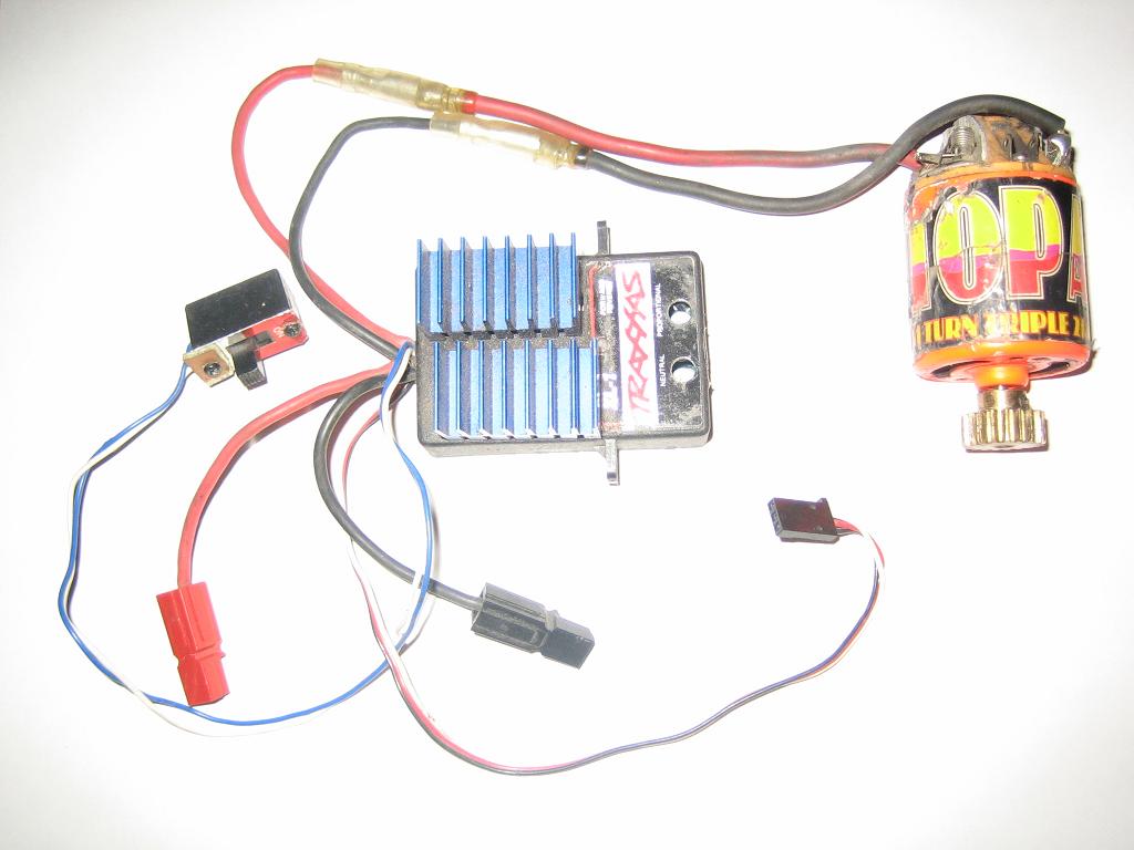
I will mostly be talking about RC servos, but you will also be able to connect a RC speed controller since they use the same technology. These speed controllers are made up of power MOS FETs to allow 12v at 50A+ to control the speed of a motor via PWM.
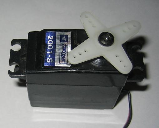
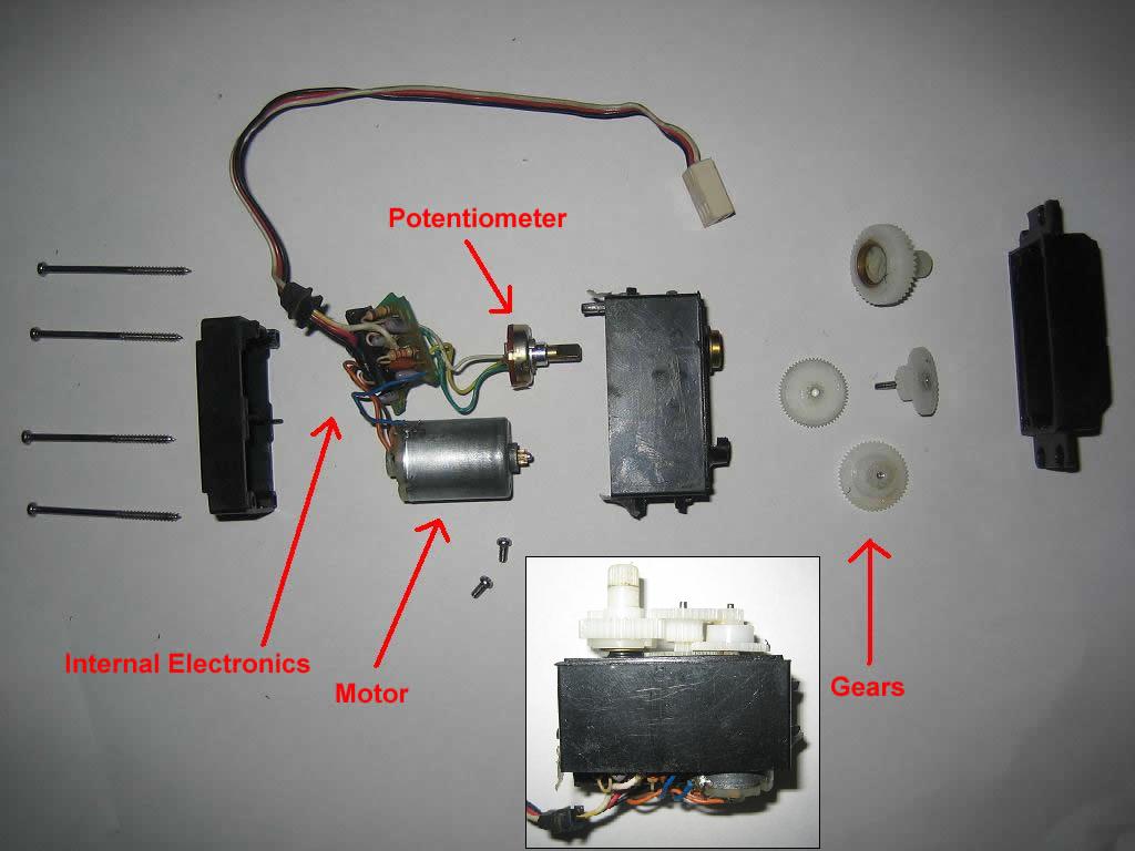
The only way to really know how something really works is to take it apart! I found some gears, a potentiometer some electronics and a motor. The servos gears are to give it the strength it needs to move whatever it is you want to move in your project. The servo knows it's position by reading a voltage off the potentiometer that gets turned by the gears which of course gets turned by the motor. After a signal is given, the servo will move to the correct location.
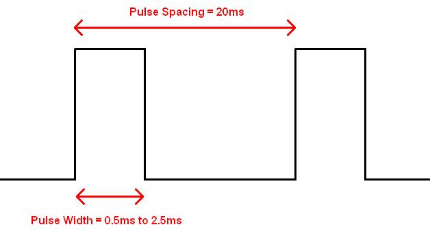
To control a servo, we need to send it a PWM (pulse width modulation) signal. Thankfully it will all be taken care of by the Jallib library I have created. A pulse will be sent every 20ms, and each pulse will be a width between 0.5ms and 2.5ms. The pulse width will vary depending on the position you have chosen. Servo pulse width required can very depending on the servo manufacturer, therefore the library has been created with some default values that you may change to get a full movement from left to right.
Here's a YouTube video of one servo moving and it's signal on my oscilloscope: http://www.youtube.com/watch?v=zA3anG0YZD4
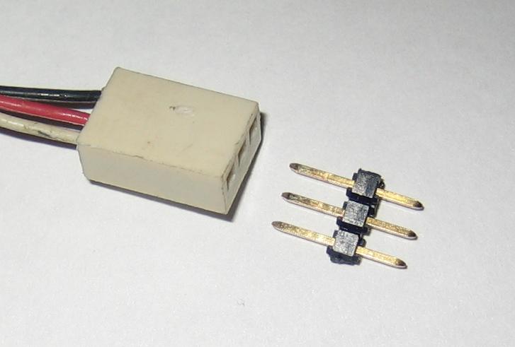
Servos come with a verity of connector types but always have 3 wires. One is ground, one is power and the other is signal.
Here's an image of my RC servo connector (left), I will use some pins (right), to plug my servo into my breadboard.
There are two ways of implementing servos into your project. You may either have your servos connected to your main PIC, or to an external PIC. For smaller projects you will choose to control your servo from your main PIC, this is the method I will show you.
If your main PIC is needed to run some heavy code, or if you need more then 24 servos, you may wish to use external PIC(s) via I2C interface. There is a library and two samples for using an external PIC via I2c bus. I will not discuss this method here.
Servo control via your main PIC
This method will allow you to plug up to 24 servos into your main PIC. Any digital capable I/O pin on your PIC should be able to run your servo signal, always lookup your pin in the datasheet. Use a pull up resistor on open drain pins. You will need to choose a PIC with a hardware timer, 8 servos can run on each timer module.
The library supports timer0, timer1 and timer3. You can do a quick search for "timer0 module" in your datasheet to see if you have a timer, most PICs do have at least one timer. The library will give you an error if you if you do not have a timer when you try to compile your code.
I have chosen 18F4620 (3 timers), but I have also tested it on 16f877a (2 timers), and 18f452(3 timers) with the same schematic.
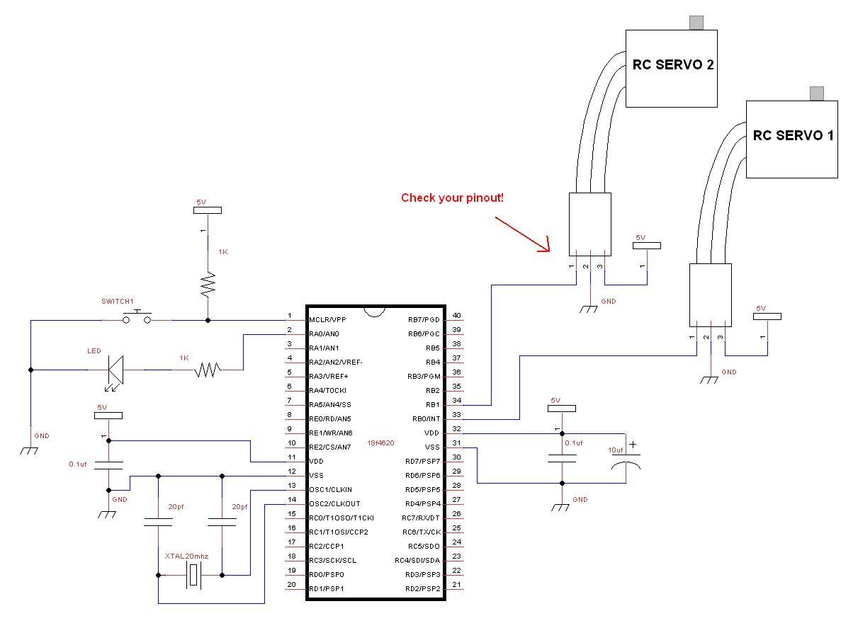
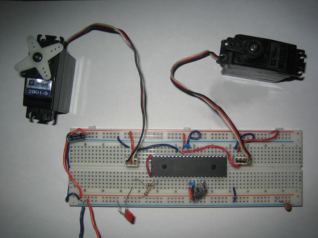
Build your circuit
The schematic is very very simple, just take your blink circuit and plug in your servo.
The Code
Since your main PIC will be controlling the servos, the PIC is acting as a master device and therefore we will be using the servo_rc_master library.
The library can be found under Jallib SVN at trunk\include\external\motor\servo\servo_rc_master.jal
The sample can be found in the Jallib SVN at trunk\sample\18f4620_servo_rc_master.jal
You can access the Jallib dowload site at http://justanotherlanguage.org/downloads
Let's start by including your PIC, and disable all analog pins
-- include chip
include 18f4620                    -- target PICmicro
pragma target clock 20_000_000     -- oscillator frequency
-- configuration memory settings (fuses)
pragma target OSC  HS              -- HS crystal or resonator
pragma target WDT  disabled        -- no watchdog
pragma target LVP  disabled        -- no Low Voltage Programming
pragma target MCLR external        -- reset externally

enable_digital_io()                -- disable analog I/O (if any)
This sample file will require 1 led, so define it now
-- led definition
alias led                is pin_a0
alias led_direction      is pin_a0_direction
--
led_direction = output
Now you may define the pins that will be used for each of your servos, I have defined 8 although I have not connected them all in my circuit.
-- setup servo pins
alias servo_1             is pin_b0
alias servo_1_direction   is pin_b0_direction
servo_1_direction = output
--
alias servo_2             is pin_b1
alias servo_2_direction   is pin_b1_direction
servo_2_direction = output
--
alias servo_3             is pin_b2
alias servo_3_direction   is pin_b2_direction
servo_3_direction = output
--
alias servo_4             is pin_b3
alias servo_4_direction   is pin_b3_direction
servo_4_direction = output
--
alias servo_5             is pin_b4
alias servo_5_direction   is pin_b4_direction
servo_5_direction = output
--
alias servo_6             is pin_b5
alias servo_6_direction   is pin_b5_direction
servo_6_direction = output
--
alias servo_7             is pin_b6
alias servo_7_direction   is pin_b6_direction
servo_7_direction = output
--
alias servo_8             is pin_b7
alias servo_8_direction   is pin_b7_direction
servo_8_direction = output
--
-- commenting out 9th servo
;alias servo_9             is pin_a0
;alias servo_9_direction   is pin_a0_direction
;servo_9_direction = output
Here we will define the min & mas movement. These values can be changed to limit the amount your servos can move. We will talk about this in detail later on, this is an important step. Changing these values will change the pulse width for all servos.
-- choose min & max servo movment / pulse size
const byte SERVO_MIN   = 50  -- default is 50  (0.5ms min pulse)
const byte SERVO_MAX   = 255 -- default is 255 (2.5ms max pulse)
Choose the timers your PIC will be using to control your servos. Each timer will take care of 8 servos. I have defined 8 servos, so I need only 1 timer. I have commented out the other 2 timers that I may use later on.
-- choose pic internal timers
const byte SERVO_USE_TIMER = 0            -- timer for servo's 1 to 8
;const byte SERVO_9_TO_16_USE_TIMER = 1    -- timer for servo's 9 to 16
;const byte SERVO_17_TO_24_USE_TIMER = 3   -- timer for servo's 17 to 24
I may now include the servo_rc_master library, and initialize the servos. Within the init() procedure, all servos will be centered.
include servo_rc_master -- include the servo library
servo_init()
If you wish to turn off a servo at any point in your program. This will turn off the servos motor by keeping the signal line low. You may set or unset the on/off bit for any servo as follows:
-- use this to turn off a servo
;servo_1_on = FALSE
Sometimes the servo you have may move in the opposite direction that you would like it to, so here you have an option of switching a servos direction. I have also noticed that some types of servos move in the reverse of others.
-- use this to reverse a servo
;servo_1_reverse = TRUE
The init procedure does center all servos, but you may want to start your servo at another location. Since I did not leave any delay yet, the servos did not actually have time to move to there center position.
I am going to center the servos again to show you an example of the correct way to move a servo. After I give the servos there move position, I will wait for 1sec so they have time to move to center.
You can use various delays or move in increments to slow the servo movement speed. 127 is center.
-- example center all servos
servo_move(127,1) -- center servo 1
servo_move(127,2) -- center servo 2
servo_move(127,3) -- center servo 3
servo_move(127,4) -- center servo 4
servo_move(127,5) -- center servo 5
servo_move(127,6) -- center servo 6
servo_move(127,7) -- center servo 7
servo_move(127,8) -- center servo 8
;servo_move(127,9)

_usec_delay (1_000_000) -- wait for servos to physically move
Now I will create my main loop and have 2 of the servos move to various positions.
-- example moving servos one and two and blink led
forever loop

   servo_move(255,1)
   servo_move(0,2)
   _usec_delay (1_000_000)
   led = !led

   servo_move(127,1) ;servo 1 centered
   servo_move(127,2) ;servo 2 centered
   _usec_delay (1_000_000)
   led = !led

   servo_move(0,1)
   servo_move(255,2)
   _usec_delay (1_000_000)
   led = !led

   servo_move(127,1) ;servo 1 centered
   servo_move(127,2) ;servo 2 centered
   _usec_delay (1_000_000)
   led = !led
end loop
So, that's it for the code. Simple right? I wish writing the library was that easy!
You can go ahead and turn on your circuit, you should see the led blink and the servos should be moving. Change and test your servo pinouts if needed. The two servos will move in opposite directions since my servo_move() procedure call values are different for each servo.
At this point, you should turn off the power when your servos are at the center position. We are turning the power off so you may remove the moving part on the top of your servo, and place it back on so it looks centered.
Here's a YouTube video of my two moving servos http://www.youtube.com/watch?v=QS8M07uuagY
Setting Your Servo Max & Min Movements
For my projects, I feel that it is important to set the servo min/max values. You may choose to either use the default values that I have set, or set your own. There are two reasons for setting these values correctly:
- You can get more movement out of your servo (far right to far left)
- You do not want your servo to try to move out of it's range. If your servo moves out of it's range for a long period of time, you may burn out the servos motor.
All manufacturers create there servos differently, there is no official specification for RC servos (that I know of).
So here are the steps:
- Set SERVO_MIN = 0 and SERVO_MAX to 255
- Set your servo_min values to restrict movement to one side.
Directly after you call servo_init(), you should place this
code:
servo_move(0,1)
forever loop
end loop
This will move your servo all the way to one side. You will hear your servo motor being ON all the time (not good for the motor).
- Now run your circuit and gradually increase servo_min value so the servo is at the correct location on one side. Try to get the servo to be 1mm from it's min location. You should not hear the motor running.
- Repeat step 2 by decreasing servo_max but use this:
servo_move(255,1)
forever loop
end loop
Well, looks like your all set. I hope your having fun with Jalv2/Jallib!