IR Ranger with Sharp GP2D02
Sharp IR rangers are widely used out there. There are many different references, depending on the beam pattern, the minimal and maximal distance you want to be able to get, etc... The way you got results also make a difference: either analog (you'll get a voltage proportional to the distance), or digital (you'll directly get a digital value). This nice article will explain these details (and now I know GP2D02 seems to be discontinued...)
Overview of GP2D02 IR ranger
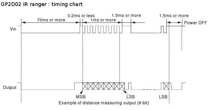
GP2D02 IR ranger is able to measure distances between approx. 10cm and 1m. Results are available as digital values you can access through a dedicated protocol. One pin, Vin, will be used to act on the ranger. Another pin, Vout, will be read to determine the distance. Basically, getting a distance involves the following:
- First you wake up the ranger and tell it to perform a distance measure
- Then, for each bit, you read Vout in order to reconstitute the whole byte, that is, the distance
- finally, you switch off the ranger
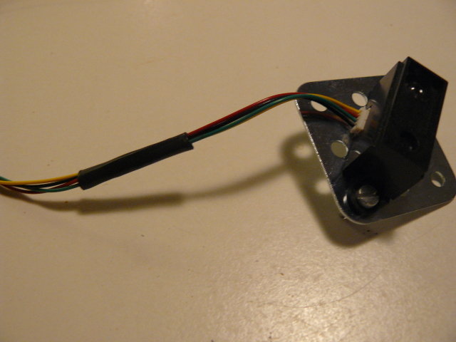
Sharp GP2D02 IR ranger looks like this:
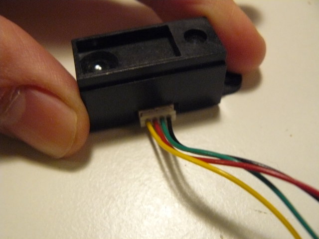
- Red wire is for +5V
- Black wire ground
- Green wire is for Vin pin, used to control the sensor
- Yellow wire is for Vout pin, from which 8-bits results read
Interfacing the Sharp GP2D02 IR ranger
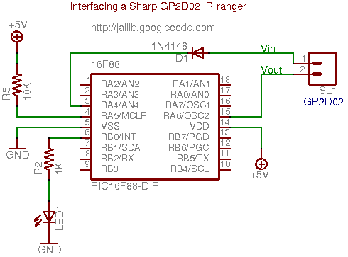
Interfacing such a sensor is quite straight forward. The only critical point is Vin ranger pin can't handle high logic level of the PIC's output, this level mustn't exceed 3.3 volts. A zener diode can be used to limit this level.
Here's the whole schematic. The goal here is to collect data from the sensor, and light up a LED, more or less according to the read distance. That's why we'll use a LED driven by PWM.
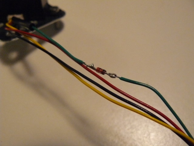
Here's the ranger with the diode soldered on the green wire (which is Vin pin, using your previously created mental note...):
I've also added thermoplastic rubber tubes, to cleanly join all the wires:
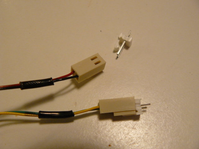
Finally, in order to easily plug/unplug the sensor, I've soldered nice polarized connectors:
Writing the program
Jallib contains a library,
ir_ranger_gp2d02.jal, used to handle this kind of rangers. The setup is
quite straight forward: just declare your Vin and Vout pins, and pass them
to the gp2d02_read_pins(). This function returns the
distance as a raw value. Directly passing pins allows you to have multiple
rangers of this type (many robots have many of them arranged in the front
and back sides, to detect and avoid obstacles).
Using PWM libs, we can easily make our LED more or less bright. In the mean time, we'll also transmit the results through a serial link.
var volatile bit gp2d02_vin is pin_a4
var volatile bit gp2d02_vout is pin_a6
var bit gp2d02_vin_direction is pin_a4_direction
var bit gp2d02_vout_direction is pin_a6_direction
include ir_ranger_gp2d02
-- set pin direction (careful: "vin" is the GP2D02 pin's name,
-- it's an input for GP2D02, but an output for PIC !)
gp2d02_vin_direction = output
gp2d02_vout_direction = input

var byte measure
forever loop
   -- read distance from ranger num. 0
   measure = gp2d02_read_pins(gp2d02_vin,gp2d02_vout)
   -- results via serial
   serial_hw_write(measure)
   -- now blink more or less
   pwm1_set_dutycycle(measure)
end looppin_A4 and
pin_A6, but to avoid confusion, I prefer using
aliases.A sample file 16f88_ir_ranger_gp2d02.jal, is available in the sample directory of the jallib released packages.
Building the circuit on a breadboard
Building the circuit using a breadboard
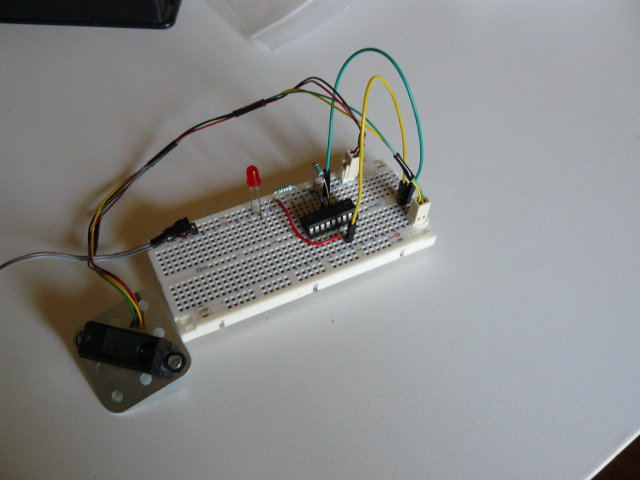
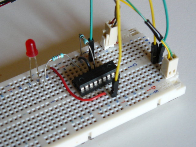
I usually power two tracks on the side, used for the PIC and for the ranger:
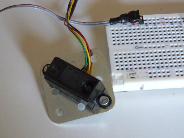
Using the same previously created mental note, I connected the yellow Vout pin using a yellow wire, and the green Vin pin using a green wire...
Testing (and the video)
Time to test this nice circuit ! Power the whole, and check no smoke is coming from the PIC or (and) the ranger. Now get an object, like you hand, more or less closed to the ranger and observe the LED, or the serial output... Sweet !
http://www.youtube.com/watch?v=l5AZwv7LzyM