In Circuit Programming
This tutorial introduces in-circuit serial programming (ICSP) for PIC microcontrollers and explains how to integrate it into your hardware.
What is ICSP?
In-Circuit Serial Programming (ICSP) lets you load firmware onto a PIC while it remains in the circuit. The programmer communicates through a small header, so there is no need to remove the device from the board each time you make a change.
For Microchip's formal definition of the protocol, see Microchip's ICSP Programming Specification.
Benefits of ICSP
ICSP streamlines development by letting you:
- Program your PIC while it remains on a breadboard circuit
- Program your PIC after it is soldered into a finished board
- Load new firmware quickly so you can iterate on code faster
- Reset the circuit directly from your development PC
- Work with surface-mount PIC devices without removing them
- Avoid bending or breaking pins from repeated insertion
- Prevent damage caused by misaligning the PIC in a socket or breadboard
- Program a remote project using tools such as VNC
- Stay comfortable while developing - my favorite setup is programming from the couch while the hardware stays in the lab
Intro to ICSP & in-circuit programming
When I first started working with microcontrollers and JAL, I chose a programmer at random from an online auction site. It supported many PIC devices, which seemed good enough at the time.
For years I removed a PIC16F877 from my breadboard, programmed it, and then placed it back into the circuit. That routine bent pins and cost a lot of development time. I eventually noticed the programmer had an ICSP output - the front panel even said "ICSP" - but I still did not understand how to use it.
After hearing more about ICSP, I examined the six-pin header on the programmer. The connections were poorly labeled, so I used a multimeter, a logic probe, and occasionally an oscilloscope to watch each pin while programming. Pin 3 was clearly ground, and pin 6 appeared unused. If you already know your programmer's ICSP pinout, feel free to skip ahead to the circuit diagrams.
Because ICSP pin assignments vary by programmer, I measured the signals while a chip was idle and again during programming. The readings looked like this:
| PIN # | While Idle | While Programming |
|---|---|---|
| 1 | 0v | 12v |
| 2 | 0v | 5v |
| 3 | 0v | 0v |
| 4 | 5v | Pulsing 0v to 5v (random) |
| 5 | 0v | Pulsing 0v to 5v (square wave) |
| 6 | not connected | 0v - can see no connection on PCB |
Get the pin names
The typical ICSP signals are VPP (program enable), VDD (target power), GND, PGD (data), PGC (clock), and an optional AUX or PGM pin. Matching these names to the voltages above reveals which signal each physical pin carries:
Pin 6 stays at 0 V, so it must be the unused AUX/PGM pin.
Pin 3 is the ground reference.
Pin 1 rises to about 12 V during programming, indicating VPP.
Pin 2 provides 5 V to the target, so it is VDD.
Pins 4 and 5 pulse while programming; they correspond to PGD (data) and PGC (clock). If all you have is a multimeter, you may need to guess which is which and confirm with a data sheet.
Most six-pin ICSP connectors follow this mapping:
| PIN # | PIN NAME | While idle | While Programming |
|---|---|---|---|
| 1 | VPP | 0v | 12v |
| 2 | VDD | 0v | 5v |
| 3 | GND | 0v | 0v |
| 4 | PGD | 5v | Pulsing 0v to 5v (random) |
| 5 | PGC | 0v | Pulsing 0v to 5v (square wave) |
| 6 | AUX/PGM | not connected | not connected |
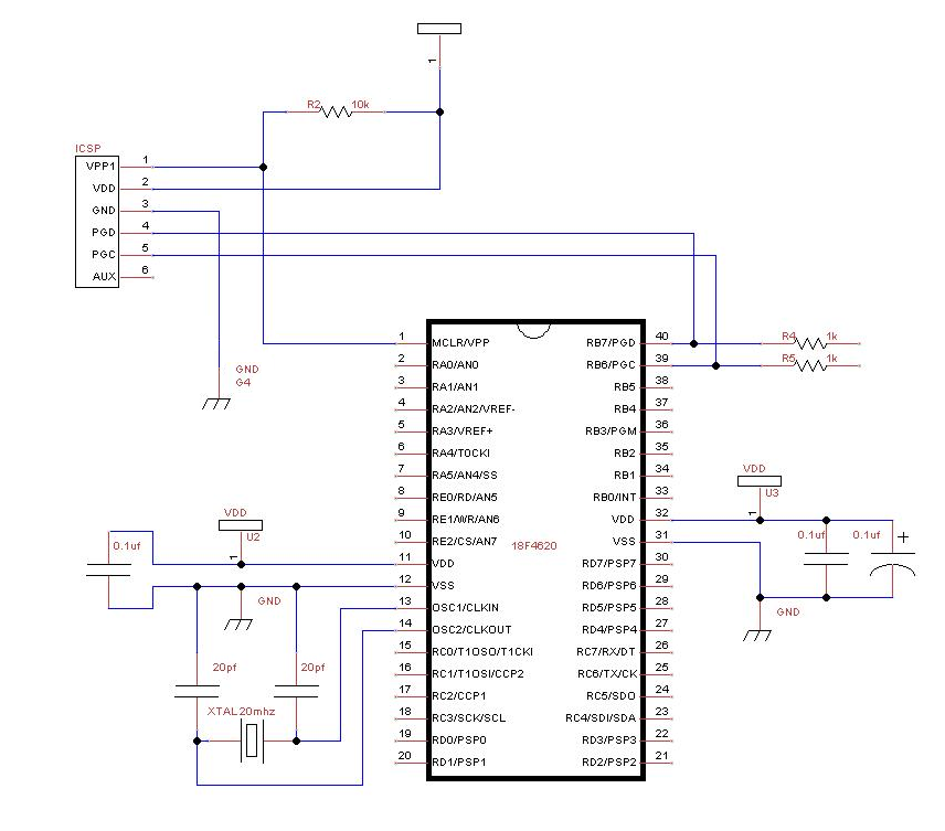
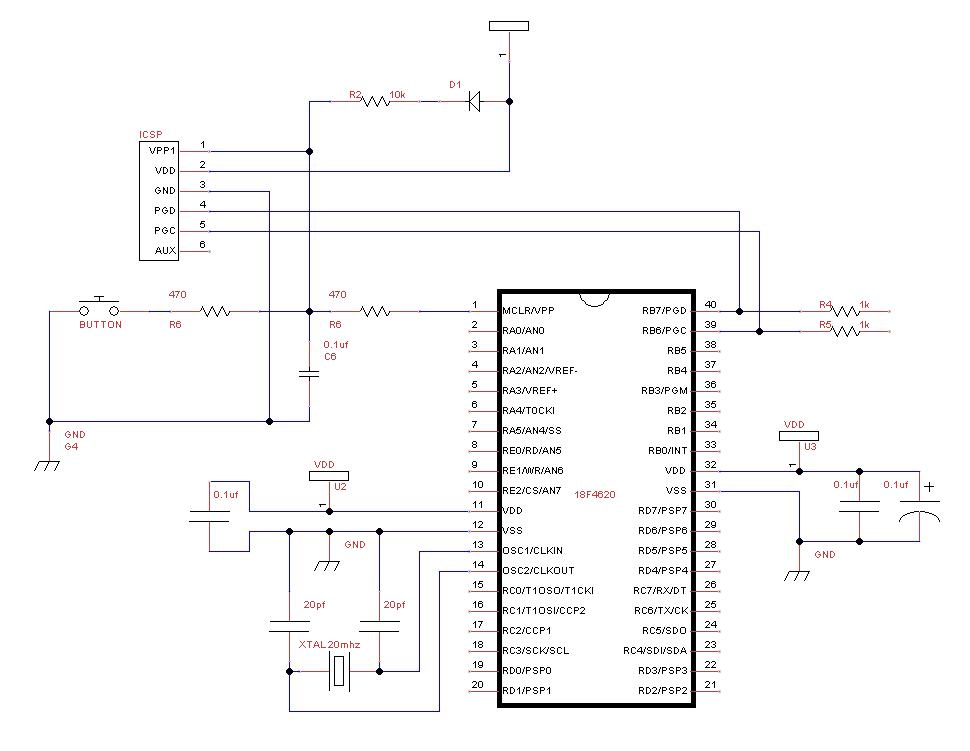
Build a circuit with ICSP
You can tie the ICSP VDD pin to your circuit's 5 V rail, as shown in the simplified schematic below. Some programmers supply power on this pin while others expect the target to provide its own supply. If your programmer does not require VDD, disconnect the wire once everything is working.
I rarely rely on power-off programming because my projects draw too much current when the supply is removed. Instead, I keep the circuit powered and let the programmer share the same ground.
GND must always connect to the project ground. Follow one of the schematics below to wire the header:
You're ready to go - apply power to the circuit and try programming your PIC.